|
Building a 4mm finescale model railway which has its basis on a
planned (but never built) railway line that never actually served the
villages of Ewhurst and Ewhurst Green in Surrey! |

|
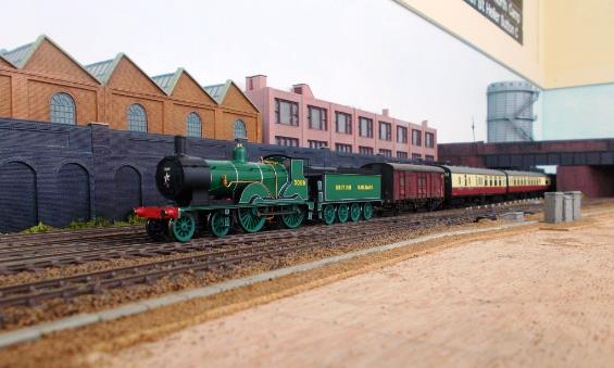
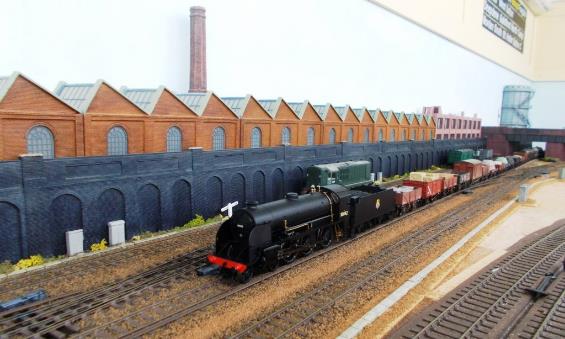
Ewhurst Green’s
station building as repainted and detailed. The platform at this location is
brick-faced with the concrete harp-and-slab construction making an appearance
with both the later-built country-end platform extensions and Up Passenger
Loop. |
Fellow Finescale Modellers,
This webpage is regularly updated as the layout
progresses.
Moving house in August 2013 to a secluded bungalow
just 440-yards from the beach (as the gull flies) brought an end to 4mm layout Apothecary Street (named after a short-lived London
junction outside Holborn Viaduct station upon where the model drew inspiration)
but provided the opportunity for a new layout, Ewhurst Green .
With my modelling deeply rooted in British Rail’s Southern Region, a design was needed that would permit operation
of full-length trains at a location which could encompass traffic from at least
two of the Southern Region’s divisions. Furthermore, the layout needed to
be operated by just one person (if required) mindful there is a limit to the
number of trains that can be realistically controlled at any moment in time.
A tall order which led to Ewhurst Green ; a
model railway which has its basis on several planned (but never built) railway
schemes in Surrey (including a c.1884 proposal from Dorking) that may have
served the villages of Ewhurst and Ewhurst Green (as a junction for Cranleigh and Guildford) on its route down
through Midhurst to conceivable join the railway along the coast near Havant, thence onto Portsmouth and Southampton. Ewhurst Green was
also in an area with which I had many past associations several decades ago.
Had a direct railway from London ever served
Ewhurst and Ewhurst Green, then it is likely these villages would have
significantly increased in size and (by virtue of the station’s goods
yard facilities) potentially attracted some local industry befitting this
(otherwise) rural area.
With Up and Down Main Lines operational, the Ewhurst Green running sessions were proving extremely popular with East Sussex
Finescale group members; particularly following lunch at our local beachfront
café under a mile away until the pandemic struck in late 2019!
However, many short video clips are regularly
uploaded to Ewhurst Green’s channel on YouTube although this is
now proving difficult to use and may be archived.
https://www.youtube.com/@ewhurstgreen
Enjoy Colin!

|
Country-end of Ewhurst Green with the separate spans of the road
bridge across the electrified main line to the coast and the Cranleigh branch
which curves away to the right behind the sub-station. The agricultural works
alongside the headshunt distracts from the otherwise semi-rural area.. |
Some layout descriptions commence with baseboard
construction. However, before any of this this happens it is important to
decide exactly what one is intending to model and how reasonably prototypical
operation could be achieved within the physical space available. In this
respect it is necessary to consider the model, not in isolation but as part of
the regional network within which it is located including its rail services,
even a reasonably viable timetable. Accordingly, our starting point is the
Layout Concept. However, readers are welcome to head straight to any of the
chapters listed below:
|
|
||||
One
|
With Maunsell
Pull-Push set 619 in the Down Headshunt, set 607 is propelled past on an Up
service by M7 no.30051. Set 607
was damaged at Eastbourne on 13th September 1961 and subsequently
disbanded. BCK 6682 was scrapped with the SO to Loose working the rest of its
days as a pull-push trailer on the Lymington branch. Both expertly weathered by TMC, set 607 was additionally renumbered as
this was not in Hornby’s range. Headcode discs are still to be fitted
to these models. On branch lines these sets often sported both a headcode
with a tail lamp! |
Southern Region
With any model railway the starting point ought to
be what does a railway-modeller want in terms of a model (whilst being mindful
of constraints such as space and budget)?
As a railwayman who followed his grandparents onto
the Southern (in my case British Rail’s Southern Region rather than the
Southern Railway) my modelling interests are fairly-well cast-in-stone. The
previous (terminal layout) Apothecary Street had been constructed as a parody
of Holborn Viaduct with cross-London freights via Snow Hill tunnel and
expanding this concept was considered.
However, in recent years the range of Southern
models that have become available make modelling of the Southern Region’s
divisions relatively straightforward, even before the many offerings by kit
manufacturers is considered. So, when Bachmann had brought out its marvellous
model of Thomas Myres 1880-1883 LBSCR station buildings the opportunity to utilise one of
these couldn’t be ignored.
Geographical Location
In building a model railway, one really important
factor is its geographical location; in the case of Ewhurst Green somewhere on
the former Southern Region (obviously). Even then there were distinct
differences between the South Western, Central and South Eastern Divisions and
could a model which could realistically incorporate stock from all three
Divisions (SWD, CD and SED) be created whilst using the Thomas Myres ex. LBSCR
station building?
|
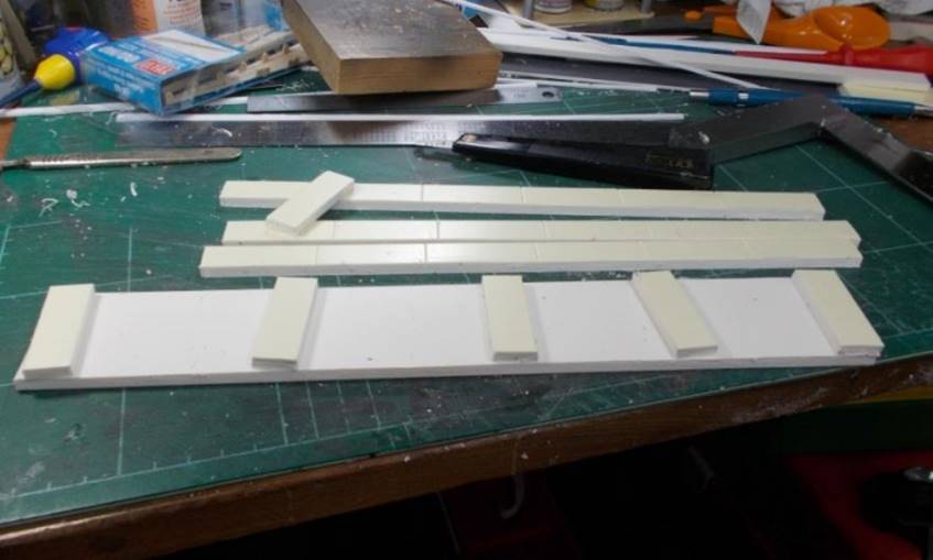
The Up Side waiting
room and subway cover (as modified and repainted) awaiting completion of the
station’s platforms. |
Thomas Myres
Thomas Myres was first asked to
design the replacement station building at Hassocks (1880), thence those
required for the secondary railway lines built in East and West Sussex Hailsham
to Eridge (1880), Chichester to Midhurst (1881), Lewes to East Grinstead (1882)
and Haywards Heath to Horsted Keynes (1883); a total of eighteen buildings.
Ewhurst Green’s replacement station building could have made the total
nineteen; perhaps more with other stations along the route !
Use of this building design would set the layout
firmly in Central Division (ex. LBSCR) territory with some limited scope for
South Western or South Eastern Division workings. However, historical design
along with a sprinkling of modeller’s licence can push the bounds whilst
still remaining reasonably credible.

|
Visiting SR Malachite
N15 746 Pendragon hauls set 209 on an Up London service through Ewhurst
Green. |
Credibility
The next stage was to identify a reasonably
credible location for the station and the potential services that could exist.
Obviously, this isn’t an essential step, but it does help in terms of
what type of services could have run and the rolling stock required. A credible
backstory will assist in developing the layout and its design towards providing
a model that will look the part. In this respect railways that were planned but
never built provided inspiration.
However, any station (and the services it could
have seen) would have to be operationally manageable by myself; there is no
point in building a layout that takes a team of operators to run it. On that
basis the favoured option was for a junction station where trains (circulating)
on the Up and Down main line essentially form the backdrop for the branch
line’s operating sequences.
In terms of appearance part of the overall concept
was for none of the scenic track to remain parallel to the track-room’s
rear wall and that a less-is-more approach was intended.

|
Visiting H2 Brighton Atlantic 32424 Beachy Head heads south
through Ewhurst Green. Behind the locomotive is a CCT fitted with cycle
hangers. |
Era
Hassocks Gate station opened on 21st
September 1841; now called Hassocks (code HSK) its first building was to a design by David Mocatta. However, it was Thomas Myres who designed its
replacement which was built between December 1880 & August 1881 by James Longley & Co of
Crawley. Sadly, this
building was also demolished by British Rail in 1973.
Accordingly, with Myres architecture this could
suggest either an opening date of the model railway’s station as being
circa 1880-1884, else a replacement station building being erected during this
period. The date of opening for the railway does provide a degree of historical
context.
Notwithstanding, the actual period being modelled
would be essentially within the period 1954 to 1962 although
concentrating within the middle of that timescale. As the model develops,
thoughts are collecting towards narrowing that timescale down to a specific
year or even having two distinct running periods with slightly differing stock.
Certainly, the scenic details would not significantly change across such a
relatively small period.
|
An unlikely photograph
for a real Ewhurst Green. However, one of the joys of running sessions
permits visiting early BR Blue liveried Merchant Navy 35024 'East Asiatic Company' to pass BR
Green liveried no.35011 General Steam Navigation
; the latter being a recent metal-bodied release under the Hornby-Dublo brand
(albeit in lined blue 3-rail packaging). |
Liveries
In terms of rolling stock quite a few coaches
retained Southern Railway post-war Malachite green into 1956 (some even beyond)
without receiving BR’s Crimson Lake (and Cream). Following the abolition of Second-class on 3rd June 1956 (at which time Third-class was immediately
renamed Second-class), the following month (July 1956) saw significantly
changes to liveries with Crimson Lake (with or without Cream) being rapidly
replaced by Southern Region Green far quicker than would have happened under
the usual ten-year repainting cycle at Lancing Carriage Works (repaints took
place instead of the 2 yearly varnishing).
During 1956 /1957 there was quite a mix of post-war
Malachite Green (with BR typeface), Crimson Lake (and Cream) and BR(S) Green.
Occasionally it was difficult to see a huge difference between post-war
Malachite carrying multiple layers of varnish and BR(S) Green.
1959 was the last year for Maunsell corridor sets
to be seen running in Crimson Lake & Cream (CLC) livery; this also saw the
demise of a lot of non-corridor stock with much still in Crimson Lake (CL).
Nevertheless, on the Southern Region many Mk1 3 Cor & 4 Cor (corridor
coach) sets weren’t repainted CLC to Green until 1961 (a few even lasted
into 1962); this being in part due to the varnishing undertaken at Lancing
Works every two years or so. 1959 also saw the first of the UIC yellow First-class cantrail bands.
A number of Southern Railway steam locomotive
classes were withdrawn very shortly after nationalisation with more
disappearing mid-fifties onward, thence with the stock associated for the 1959
Kent-coast electrification; these all being interesting periods of change.
With such a variation in rolling stock and liveries
it has been decided to keep the period as a concise range (rather than a
specific date) although this range can be narrowed for any given running
session.
Notwithstanding, individual trains are normally
formed of stock that would have run together both in terms of livery and
division. For example BRCW Cromptons would not have
run with a CLC-liveried Maunsell corridor set.
|
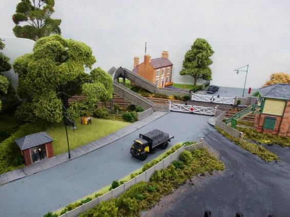
With a tree
temporarily removed from beside the LSWR wooden gates into the coal yard, an
uninterrupted view is enabled of the bus shelter, Level Crossing, concrete
footbridge thence Lavender House with its H type television ariel mounted on
its chimney. |
Less is More
The
room housing Ewhurst Green has considerable length. However, in order to try
and create greater realism, a linear layout with its scenic track parallel to
the back wall of the track room was simply not going to happen.
Firstly,
whilst the central scenic section of the layout is constructed on a straight
32” wide baseboard, the other two-thirds on either side taper outwards to
around five-feet in width (the baseboard design still places everything within
arm’s reach more on this later). This arrangement helps to break up the
otherwise linear appearance of the scenic section.
At
either end, the double-tracked main line curves around from the storage loops
on tracks hidden from view (at the country end the double-tracked branch
similarly curves again out of sight). The scenery is designed to place these
out of immediate view whilst avoiding the old cliché of disappearing
into a tunnel.
However,
once the mainline becomes visible, it comprises two long straights split by a
large radius curve (position mid-way along the station’s platformed
section). This design has a number of benefits with the principle two being:
(1) the main scenic
running lines are not parallel to the rear wall of the model room and
(2) space is created
between the main lines and the back wall for the station building, forecourt
and Down bay platform.
Even
the long retaining wall (with agricultural works atop) is constructed on a
taper relative to the back wall. In terms of railway history, the factory originally stood atop a cutting
and (with the enlargement of the station) the cutting had to be replaced with a
retaining wall in order to enable a headshunt alongside the Down Main.
Visually,
the front of the station building cannot be seen but the (arguably) more
interesting platform side can. In terms of operational accessibility, this
arrangement allows the platform loop and goods loop to be on the
operator’s side of the main line (and station). Furthermore, the tapering
boards can be used for fanning out the station’s goods yard and sidings
whilst leading the scenery into the two curved boards which hide the tracks are
they curve round to the storage loops.
Finally,
the decision was made not to crowd the baseboards with track; once again this
was to try and improve the appearance of realism. As the old adage says,
‘Less is more’.
Two
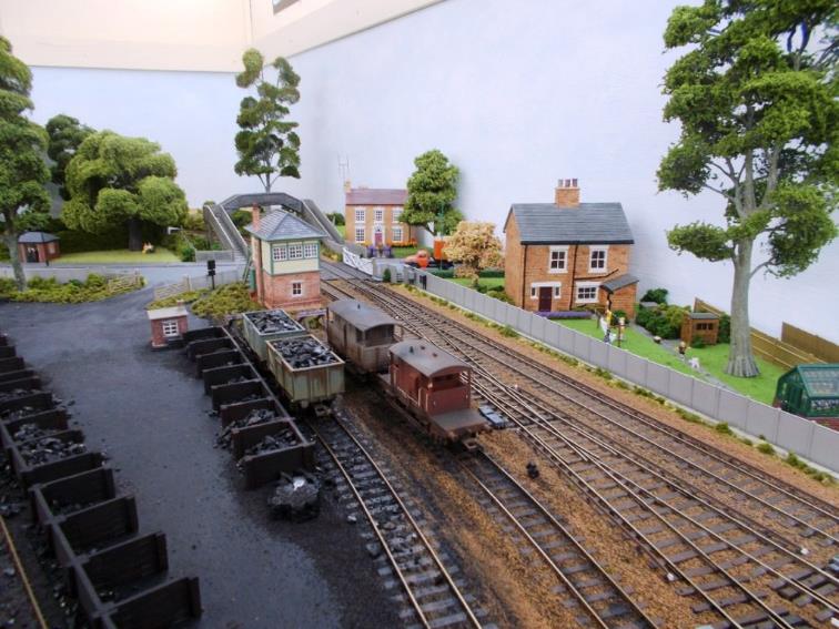
|
As construction progresses Ewhurst Green is starting to look
greener and far more rural. With the coal yard well underway, the headshunt leading up to
the Signal Box has been laid. Lavender House sits beyond the Level Crossing
now has its MacKenzie & Holland gates. To the right of Cherry Cottage, just visible is the concrete
coal bunker behind the half-buried and overgrown Anderson shelter with garden
shed alongside. Washing is being put out whilst a boy plays with his dog.
Flowers fill the greenhouse just visible on the far right. Behind the greenhouse and tree there is an access road between
the two wooden fences that leads to some lock-up garages & alley to the
station. |
Setting the layout’s location can assist in
its design, so what should a railway-modeller consider?
Having ruled out modelling a real station (I admire
those modellers who do) and based on what was wanted from the model versus the
limited space available, the next best thing would appear to be a credible but
fictitious station at a real location. In this respect it becomes quite
difficult finding such a location, for most candidates already have or had a
station. However, one possible location stood out in terms of a potentially
credible location on a proposed but never built railway line.
Furthermore, the name Ewhurst Green ticked all the
right boxes in terms of an appropriately sounding Southern Region name.
There are two village locations called Ewhurst
Green one in Surrey (near Cranleigh), the other in East Sussex (near Bodium);
thus, providing the opportunity to be slightly indistinct with the location if
ever required. Certainly, Ewhurst Green (and nearby Ewhurst) in Surrey could
have fitted in with unfulfilled c.1884 plans to build a railway from Dorking
serving Cranleigh thence down to Midhurst.
There is also a
Ewhurst Park near Basingstoke and a Ewhurst Manor in the parish of Coneyhurst,
West Sussex (along with a Coneyhurst Manor in the parish of Ewhurst, Surrey).
Whilst both Ewhurst Green locations provide
opportunity for Central & South Eastern Division services, Surrey could
additionally link directly to the South Western Division as well as forming an
alternative route to several important locations, thus opening-up the traffic
passing through the station.
It was equally surprising that the website www.EwhurstGreen.com was available!
East Sussex
Ewhurst Green (East Sussex)
The East Sussex village of Ewhurst Green sits not
too far south-west of the Kent & East Sussex Railway, which at this
location passes east west along the Rother valley at Bodium; this being already
served by a light railway built through relatively a sparsely populated rural
area. The nearest main line to London passed through Robertsbridge situated
between the sizeable towns of Hastings, St Leonards-on-Sea and Royal Tunbridge
Wells. Accordingly, the scope for credibly modelling an ex. LBSCR mainline
railway through this Ewhurst Green was sadly virtually nil.
Surrey
Ewhurst Green (Surrey)
The name Ewhurst
derives from the Old English 'hyrst', meaning 'wooded
hill', and 'iw' meaning 'yew tree'; the first
recorded spelling appears to be Iuherst from 1179.
Historically Surrey’s Ewhurst and Ewhurst
Green may have come close to being served by the railways. In terms of routes
to Midhurst, 1845 saw consideration to build a line from Guildford through
Godalming, Haslemere and Midhurst to Chichester. However, LSWR’s Midhurst
- Petersfield did open in 1864, LBSCR’s Midhurst - Pulborough (Hardham
Junction) in 1866 and Midhurst Chichester in 1881 (the first sod of the latter
having been cut back in 1865 passenger traffic ceasing in 1935). Passengers had
to wait until 1925 for a combined Midhurst station (services to Midhurst were
withdrawn in 1955).
With the SER considering a route from Betchworth to
Portsmouth, Ewhurst Green could have been a junction station on a
thirty-seven-mile LBSCR route between the existing railways at Holmwood and
Westbourne.
Mixing
historical proposals with imagination it is conceivable such a railway line
could have left the Dorking to Horsham Railway at Holmwood passing through a
station at Forest Green to reach Ewhurst Green (due south-southeast of the village). In terms of railway
construction this would have been built late in the day .
A junction
off the London-end of Ewhurst Green station would have permitted the
line across from Warnham and Horsham (passing through Oakwoodhill station) to
join.
Whilst
there could have been a junction at the Country end of Ewhurst Green taking a double-tracked branch-connection across to
the 1865 Horsham to Guildford railway and into station at Cranleigh (itself having become a passing loop in 1880 as those at
Bramley and Baynards were proving insufficient) it is possible that the 1865
route was not built in favour of Horsham Ewhurst Green - Cranleigh.
From Ewhurst Green this main line may have
passed through Loxwood thence Gennets Viaduct across the valley (both Wey & Arun
Junction Canal and the River Arun) to Plaistow
station (actually sited close to Ifold). In order to
avoid tunnelling immediately north of Midhurst
the line had to approach from the north-east so serving the villages of Kirdford and Lodsworth.
Midhurst to Chichester would
have been under construction at this time but with this new line now laid as
double track through Cocking tunnel and Cocking
station to Singleton (with its four
platforms and nearby Goodwood racecourse) to a junction just west of East Dean.
However, Singleton to Chichester was
probably still laid as a single track providing a useful route towards
Worthing, Hove [actually] and Brighton.
West from Singleton the line may have entered two
further tunnels (under Heathbarn Down thence
Stoughton Down) necessary to provide a fast alignment into Havant. This could
have given rise two further stations (Stoughton
& Walderton thence on a falling grade to Westbourne). The Brighton to Portsmouth
Railway was joined just east of Warblington.
The
possible route is described in detail here at the bottom of
this article.
This made Ewhurst Green
(Surrey) a respectable candidate for the model railway.
|
|
|
|
Route map shewing the
railway from Dorking through Ewhurst Green with the branch to Guildford via
Cranleigh thence Bramley & Wonersh also the branch to Horsham via
Oakwoodhill and Warnham. |
|
Local Development due to the Railway
As a junction with a railway through to Cranleigh
(thence onto Guildford and Reading via the SER route) Ewhurst Green could have
grown significantly through being served by (in time) an electrified railway.
So, it eventually became a starting point for suburban services into London
(along with some freight handling).
Nearby Cranleigh doubled in size in the first forty
years after the building of the 1865 Guildford to Horsham railway line and it
is probable that Cranleigh would have grown much further had it been on a
direct railway line /service to London (thus being attractive to commuters).
With rail congestion in Guildford’s southern approach, an alternative
route from Cranleigh to London via Dorking might have been an attractive
proposition post-grouping.
However, villages such as Ockley and Capel did not
grow as significantly; perhaps their respective distances from their station
and the slow low-frequency rail service made a significant contribution to this
lack of growth, particularly when the London suburbs were still expanding.
Any proposal for a branch to Holmbury
St. Mary was never a credible prospect; even local bus services were not that
frequent.
Midhurst could also have grown significantly from
having direct routes to both London and Portsmouth, it is also probably that a
few of the villages with stations along the line would have experienced some
increase in size. However, it must also be noted that it was only in recent
years did many places served by the Mid-Sussex line (a.k.a
Arun Valley line) south of Horsham undertake significant development.
Accordingly Ewhurst and Ewhurst Green could have
similarly expanded, particularly around a well-served station.
The building of such a route (including its
subsequent early-1925 electrification as part of the Waterloo to Dorking
scheme) could have led to interesting connotations in respect of railway
service patterns although in reality Ewhurst Green (plus Ewhurst and Walliswood) would probably never have grown to sufficient
size to be as busy as portrayed by the model.
|
Route map shewing the
railway from Dorking |
Route Engineering
Imagination could reasonably assume this route was
reasonably well-engineered being intended to provide a faster alternative (to
the Mid-Sussex line) between London and Portsmouth as well as competing with
the LSWR’s Pompey Direct; - a 1858-built and privately constructed
curvaceous and graded line south from Farncombe (that was offered for sale to
the LSWR, LBSCR and SECR).
In determining the route (and with a background in
railway /tramway alignment design) the topography was examined to confirm such
a route would have been reasonably practicable.
In terms of distance this route would have been
around ten miles shorter from Victoria to Havant than via Ford and only around
three miles longer than Waterloo to Havant via Guildford.
In Southern Railway days this imaginary line could
have also provided a potentially viable route to Fareham with trains
terminating at either Southampton Terminus or Southampton Central.
Post-grouping could have also opened-up limited services into Waterloo via
Raynes Park (including as a useful diversionary route). Although quickly DC
electrified, like many places in Sussex its branches were not.
However, with this line having been opened it is
questionable as to how long Midhurst Pulborough and Midhurst Petersfield would
have survived; probably closing earlier than they really did. Midhurst
Chichester would have probably survived having strategic use as an east-facing
connection onto the Havant to Brighton line.
|
An unidentified
Birdcage trio C nears Gomshall
& Shere behind BR Standard 4MT no. 76054 on the 5.31pm Redhill to Reading South
service (1st June 1957). Ben
Brooksbank (Geograph/CC-by-SA) |
Dorking connections
Holmwood to Cranleigh & the coast (proposed)
On more than one occasion, the LBSCR
considered the provision of link between its Portsmouth mainline passing
through the rather isolated district lying to the south of Leith Hill and Pitch
Hill. The SER had similar aspirations of its Redhill Dorking route.
In 1897, plans were prepared for a
line from Holmwood to Cranleigh; a distance of about 8 miles. A bill was
submitted to Parliament in the ensuing year but was withdrawn in the face of
opposition from landowners in the Holmwood district. The scheme was never
revived.
Ewhurst Green model railway takes much
inspiration from this scheme.
Betchworth to Holmwood (proposed)
Early railway proposals at Dorking appear to have
included a line diverging from the Redhill to Reading railway across to
Cranleigh. However, there was never a connection linking Betchworth to Holmwood
as traffic would have travelled via Three Bridges. The question is would such a
spur been useful to connect to Ewhurst Green (etc) and the answer would have
probably been not unless part of a scheme to give the SER a route right through
to Portsmouth. However, there would have been great difficulty in obtaining a
viable route that would have satisfactorily served the town of Dorking
(including Deepdene station) given the topographical constraints of the area.
From Croydon, LBSCR passenger trains would have
been routed via Sutton /Epsom /Dorking although for the SER the journey time to
Dorking via Redhill wasn’t much different. However, if the SER had built
the line, then this spur may have come into being although come SR days it
would have probably found little favour with Waterloo providing the faster
services to Portsmouth.
Freight from (say) Norwood Yard would just have
easily reached Ewhurst Green via West Croydon. However, had there been direct
connection across the top to Tonbridge at Redhill then the situation may have
been very different for traffic to /from Kent into Hampshire.
Deepdene to Holmwood (spur closed)
There was a spur linking Deepdene and Holmwood
(closed 1900 /reconnected 1941-47). This only ever appears to have seen minimal
use very early-on for South Eastern Railway race-trains to Epsom.
However, during 1941-1945 it’s reconnection
onto the Redhill Reading line (since 1900 it remained as a siding off the
Horsham line) could have provided alternative routings in the event of
blockages (including from enemy action); in particular, enabling the movement
of breakdown cranes.
Was it therefore plausible that this spur may have
been retained in 1900 to create a means of diverting freight traffic to Ewhurst
Green instead of through Cranleigh? Probably not as there would have been
little or no commercial need. Furthermore, freight use would be restricted by
the steep grades away from Deepdene up to Gomshall thence down to Shalford
(each around 1 in 100); particularly with more practical routes being
available.

|
LMS-type
Ivatt 2MT No. 41301 runs around down Horsham’s platform 3 having just
arrived on a service from Guildford on 5th June 1965. Ben
Brooksbank (Geograph/CC-by-SA) |
Horsham connections
The Guildford Cranleigh Horsham railway provided a
cross-country rural railway with onward connections to London (and other
destinations) at both Guildford and Horsham. However, with the building of and
connection to Ewhurst Green would bring changes including potentially splitting
the services from Guildford and Cranleigh between terminating at Ewhurst Green
and Brighton (via Horsham). Such a layout would mean any though traffic from
Reading (and beyond) to Brighton via Horsham & Henfield was not constrained
by the actual need in reality for changing /reversal at Horsham (else
inconveniently changing at Christ’s Hospital) to continue onward to
Brighton via Henfield.
Although there was a spur at Christ’s
Hospital enabling trains to travel directly from Cranleigh to Ichingfield Junction thence to Brighton via Henfield, this
appears to have been taken out of use before WW1. In addition, the spur could
not serve Horsham or provide any passenger interchange onto the Horsham to
Arundel railway which no-doubt contributed to its demise.
There were three stations between Cranleigh and
Christ’s Hospital: Baynards, Rudgwick and Slinfold. In terms of Baynards Park estate this is located
equidistant between Baynards and Ewhurst Green stations and there would
probably have been minimal case for Baynards station. Passengers for Rudgwick could have changed at Ewhurst Green else Alfold.
It is therefore possible that one of five options
that may have occurred:
1. The
line through Cranleigh passed to the north of the town to Ewhurst Green and its
main line. Immediately north
of Ewhurst Green there was another junction for a line heading south-east
passing through a station at Oakwoodhill before joining the Dorking to Horsham
railway line at Warnham. This would provide a cross-country direct route
(without reversal) from Reading - Guildford Cranleigh via Ewhurst Green through
Horsham and onto Brighton.
That the spur at Christ’s Hospital was taken
out very early on the viability of such a connection without serving Horsham
was probably highly unlikely. Rudgwick and Slinfold would have been served either from Horsham or
Ewhurst Green or did the main line serve Rudgwick
instead of Alford...
2. From Cranleigh the railway would have simply been
constructed to Ewhurst Green instead of reaching Horsham. With Ewhurst Green
being close to Baynards the case for a station there could be much reduced; the
actual need for Rudgwick and Slinfold
stations also needing consideration.
3. The Guildford - Cranleigh - Guildford railway (it
was named Cranley up to 1867) was constructed with a spur from Cranleigh to
Ewhurst Green. With Ewhurst Green close to Baynards the case for the latter
station could have been much reduced.
4. The railway would have provided a spur south off
the Ewhurst Green Alfold railway south-east down to join the Cranleigh Horsham
railway close to Baynards station. This option would have meant Cranleigh to
Horsham trains could call at Ewhurst Green (albeit with a reversal) thence at Rudgwick and Slinfold. However,
the viability of such a spur was probably questionable both operationally and
in terms of journey times for Guildford /Cranleigh passengers to /from Horsham.
5. The two railways would have
simply crossed. However, it is unlikely that the potential for a faster
Cranleigh to London connection would have been ignored by the LBSCR.
In respect of the model’s station operation,
it is assumed option 1 had been implemented.

|
Hawker Hunters parked outside the final assembly hangers situated on
the northern side of Dunsfold Airfield. |
Dunsfold Airfield
Built in just twenty-weeks during 1942 by the First
Canadian Army (mainly the 2nd Battalion Royal Canadian Engineers), it is
conceivable that Dunsfold Airfield could have served by a lightly-laid
freight-only branch from a well-connected main line (in reality no such facility was ever provided off the nearby Horsham to
Cranleigh branch line).
Accessed from Cranleigh, the branch curved
significantly to follow the land topology (in order to speed construction and
reduce cost) across Cranleigh Road (close to Elmbridge Road) in part following
the route of the Wey & Arun Junction Canal (by 1868 canal traffic had virtually
ceased with an Act of Abandonment passed in 1871) until it turned to cross Horsham Road near the
northern end of the (then new) Alfold by-pass (itself built to accommodate the
airfield) and into the airfield.
RAF - Dunsfold Airfield was used by the
Royal Air Force, Royal Canadian Air Force & the Royal Dutch Naval Air
Service. At the end of the war Dunsfold Airfield was used for the repatriation
of PoWs (Operation Exodus) before being declared as inactive.
Skyways - In August 1946 the airfield was
leased to Skyways Ltd as a 24-hour operations & engineering base. Skyways
Ltd employed some 1200 staff (including 350 aircrew) at Dunsfold; its principal
air-charter work being transportation of Anglo-Iranian Oil Company staff into
and out of Basra and (from June 1948) the Berlin Airlift. Unfortunately, the
end of the Berlin Airlift in May 1949 saw some 400 staff being made redundant
and in March 1950 Skyways Ltd went into liquidation. It was relaunched but this
failed in January 1952. Taken over by the Lancashire Aircraft Company in March
1952, Skyways moved to Bovington (presumably to make more room for the Hawker
Aircraft Company). After further changes the final iteration of the company
ceased in 1962 with the Skyways name disappearing in 1980.
Hawker - In 1951 the Ministry of Supply
offered the Hawker Aircraft Company the lease of Dunsfold Airfield which was
then used for the development of the delta-wing Avro 707B, Hawker Hunter and
Sea Hawk jet fighters. In addition, Sea Furies, North American F-86 Sabres and
Supermarine Attackers were refurbished at the airfield (the latter pair in two
hangars leased to Airwork Ltd from 1953-58). In October 1960, Hawker Siddeley flight tested its Hawker P.1127 prototype (which
led to the Hawker Siddeley Harrier). In 1961 Folland
Gnat test flying, and production moved to Dunsfold from Chilbolton in
Hampshire.
Given the curving nature of this lightly-laid
branch (a consequence of its rapid construction) trainloads were inevitable
small with suitable motive power limited to short-wheelbase locomotives.
As a rail-served facility it could have initially
proven useful, particularly given its relative accessibility including MoD
sites such as Bicester, Marchwood and Shoeburyness; the latter being via the
East London Line (which saw freight use through to 1966). However,
post-war saw a significant reduction in freight traffic on the Dunsfold branch;
essentially now limited to occasional vans and aviation spirit to the Hawker
Aircraft Company.
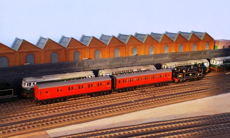
hree
|
Lord Nelson no.30863 Lord Rodney on Down express formed strengthened set
247 Formed BTK-TK-FK-BTK set 247 is strengthened with Loose TK and TO coaches
plus New Century Bar Pullman car (now
replaced with a Maunsell restaurant car). |
3. Ewhurst Green & the
Southern Region
Passenger Journey Times & Possible Services
For any credible train operation (including its
timetable) the journey times to destinations served need to be fully
understood, enabling Ewhurst Green to be considered in terms of the traffic
that could be routed through it including realistic journey times.
Ewhurst Green station
When first built, Ewhurst Green had just two
platforms on the double tracked main line with a junction leading onto the
single-track branch to Cranley and Guildford.
At the request of the United Kingdom’s Postmaster
General, Cranley was renamed
Cranleigh in 1867 as it was often
mistaken for Crawley (and vice-versa).
As traffic increased, this route to Cranleigh was
double-tracked and an additional bay platform (now platform 4) provided at
Ewhurst Green, along with the new station (Myres) station building. With the
1925 electrification, all the platforms were extended southwards and a new
eight-coach platform 1 (Up Loop) provided for the electric suburban service
that would be starting from there.
Accordingly, the station has its platforms and
freight reception road arranged as follows:
|
(a) |
Freight reception used by freight traffic, shunting
into the carriage siding and entry into the goods yard. |
|
(b) |
Platform 1 - Up Passenger Loop is used both
for terminating /through traffic off the Cranleigh branch and terminating
suburban electric services from London. There is also direct access into the
8-car electric siding. |
|
(c) |
Platform 2 Up Main |
|
(d) |
Platform 3 Down Main |
|
(e) |
Platform 4 non-electrified bay platform used
to provide a connection from London trains across the main line and onto
Cranleigh branch services. |
|
(f) |
Dock - accessed from the Down Headshunt. |
|
Note |
Platform 1 is Ewhurst Green’s only
reversible platform road whereas platform 4 is for departing services only. |
Route to Portsmouth
Back in the real world, for many years some of
Victoria’s services to Bognor Regis and Portsmouth were routed via
Dorking North (some 2hr 15min to Portsmouth Harbour compared to 1hr 35min on
the Pompey-direct from Waterloo) until they included the stops at East Croydon
and Gatwick Airport with the May 1978 re-routing of services.
A faster route via Ewhurst Green might have reduced
this 2hr 15min Victoria time by some 10 or even 15 minutes; even more without
many of the Arun Valley /Chichester stops. Certainly, some of the fast trains
to Horsham (and beyond) that used to run via Mitcham Junction (non-stop) and
Dorking were around 10 minutes faster than the present services routed via
Gatwick Airport.
It is therefore presumed that this imaginary new
line via Ewhurst Green might have just managed Portsmouth Harbour in 1hr 55mins
for fast trains either from Victoria or Waterloo; the journey from Waterloo via
the Pompey-direct being some twenty minutes quicker (1hrs 35mins). Whilst
Waterloo to Dorking was 46 minutes for the fastest suburban services, like
Victoria a non-stop journey could be 37 minutes.
The stopping journey time to Portsmouth via Ewhurst
Green would have been around 2hr 25mins, this being some 50 minutes longer than
the fast train from Waterloo (today’s services via Eastleigh and Fareham
taking around 2hr 10mins). Obviously the stopping trains served different
communities.
|
T9 no.30119 hauls Mk1
set 876 on an Up Waterloo service; this set being released new from Eastleigh
Works on 1st June 1952 in Crimson Lake & Cream livery. |
Route to Fareham & Southampton
Modern Victoria services to Southampton are more
about intermediate trips (in particular as they include the now-important
interchange at Gatwick Airport) rather than overall end-to-end journey time (today’s trains from Victoria right
though to Southampton being routed via East Croydon, Gatwick Airport and
Horsham).
Until the advent of electrification from Farlington
Junction to St Denys (in May 1990), very few trains ran direct from Havant to
Fareham; this line would have provided a regular through service without the
need to travel to Portsmouth & Southsea to change (the Waterloo fasts did
not stop at Fratton). Operating a service via Ewhurst Green would improve this
connection and give Fareham a London service but not at the expense of South
Western main line capacity between Basingstoke and Eastleigh.
In terms of London to Fareham, a route through
Ewhurst Green would have probably been achieved in 2hrs; being far quicker than
changing at Eastleigh and marginally quicker than changing at Portsmouth &
Southsea (today’s direct electric
service via Eastleigh take 1hr 35mins). Accordingly, on this model there
are regular steam services from London direct to Fareham thence onto
Southampton; these also serve the Cosham, Netley and Woolston which were (then)
comparatively large compared to other station-communities along this section of
line.
Would such a service have saved the branch to Fort
Brockhurst and Gosport? - probably not.
Cross-country Services
Ewhurst Green was one of several junctions on the
cross-country route from Brighton through Horsham to Guildford and Reading with
some services through to Alton and beyond.
Local cross-country services ran though Guildford
and Tongham to Bordon.
Race days at Goodwood also saw regional and
interregional services.
London Commuter Traffic & Cranleigh
Dorking North’s suburban services took around
37 minutes from Victoria (limited stops), 46 minutes from Waterloo and 53
minutes from London Bridge.
From London’s Victoria station, Ewhurst Green
would probably have been around 5 minutes shorter than the 53 minutes to
Horsham (timing for those trains that only stopped at Dorking North); 50
minutes from Victoria could have been achievable. This could have placed
Cranleigh at just under an hour from London on the through service (50 minutes was just achievable on selected
services from Waterloo changing at Guildford although this was often closer to
an hour). Given the how busy Guildford station was (and still is) it is
conceivable that Cranleigh London services were routed through Ewhurst Green,
including during the peak-hours.
|
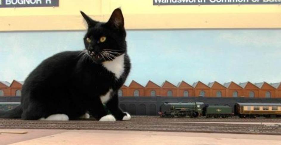
On the Branch reversible, Somer
(12mm/1ft black /white tuxedo livery) simply isn’t fazed by Schools
class no.30913 Christ’s Hospital (4mm/1ft BR Green livery) passing by
on the Up Line with visiting Pullman cars. Somer often curls up in a little box just under the
baseboards sleeping quietly despite all the trains rumbling overhead! |
4. Station Operation of the Model
The larger the layout the more there is to control, and one can only realistically hope to control one or two trains at any given time. The station layout comprises Up and Down Main lines with an Up Loop (for steam services off the branch and the start of suburban electric trains into London) and a Down Bay essentially for starting steam services onto the branch to Cranleigh and beyond.
In terms of signalling, home signals are normally
situated 440yards out from the station; this would place those for Ewhurst
Green in the fiddle yard /storage loops effectively meaning there is only scope
for having one train running on each circuit at a time. With the branch
operating from the Up Passenger Loop there is scope for a further train
operating. However, such complexity would require multiple operators.
In essence, the main line (with its through trains)
provides the window dressing for the main operational side to the layout, steam
services off the branch and the suburban services. A modest up-side freight
yard also provides for a diversion of interest.
Furthermore, I anticipate the option of operating
the layout to time rather than a sequence necessary to entertain at exhibitions
(neither my cats nor I get bored with the gaps between trains).
Chapter Five
|
An unidentified 4 CEP unit undertakes
conductor-rail clearance testing on a newly laid section of con-rail. Soon
after this photograph was taken the section of con-rail was lifted, primed,
painted and re-laid back in place. |
5.
Passenger Service Pattern
In designing a layout, it is important to consider
how it could operate in a reasonably realistic but interesting manner.
Certainly, most of the Southern Region’s electric services operated on a
half-hourly clockface pattern; this in part being down to the economics of DC
third rail operation.
Portsmouth
Some 50 minutes from Victoria, Ewhurst Green would
sit upon a basic hourly semi-fast electric service from Portsmouth Harbour to
Victoria; services serving Midhurst, Havant, Fratton and Portsmouth &
Southsea (calling all stations between Ewhurst Green and Westbourne).
Warblington was served by the Chichester to Havant services.
Set atop of this basic hourly electric service was
an hourly fast electric service Victoria Portsmouth Harbour via Havant, Fratton
and Portsmouth & Southsea (which did not stop at Ewhurst Green). The
platforms at Ewhurst Green are configured electrically to enable the splitting
/coupling of electric units should the service pattern alter at some future
date.
Fareham & Southampton
There would have been an hourly steam-hauled
Victoria Southampton fast service passing through Ewhurst Green running via
Havant to serve Fareham; a significantly-sized town which (following the
opening of the Pompey-direct) did not then enjoy a regular direct service to
London. An additional peak-hour service ran from Waterloo. It is envisaged
these Fareham /Southampton services would (at set times) contain dining
facilities /Pullman car.
London Commuter Traffic
Situated at the end of suburban services, there was
just an hourly off-peak stopping service to London Bridge (the other
half-hourly suburban service terminating at Dorking North). With the exception
of the London Bridge stoppers, rush-hour fast services travelling north would
just call at Dorking, semi-fast additionally at Leatherhead, Sutton and Clapham
Junction.
Forest Green station would only be served by the
hourly London Bridge suburban service; Holmwood by Dorking to Horsham trains.
Cross-Country
Guildford, Reading, Horsham & Brighton
On the Guildford branch there would be a
half-hourly service; one loco-hauled each hour from Brighton (via Horsham)
through to Cranleigh, Guildford and Reading with the other rail motor
(pull-push) from Ewhurst Green terminating at Guildford; prior to 1957 this
having continued to Wanborough, Ash, Tongham, Farnham, Bentley and Bordon.
Additionally, there was a rush-hour service (loco-hauled) from Cranleigh into
London Bridge.
There was also a couple of through services from
both Brighton and Horsham through to Guildford thence onto Alton, Winchester,
Eastleigh and ultimately Southampton Terminus, although not advertised as such
in the public timetable. These were mostly for the carriage of mail and
newspapers, although still carried local passenger traffic.
All this is of course concocted simply to make
interesting railway operations rather than any probable commercially viable
service!
Chapter
Six
|
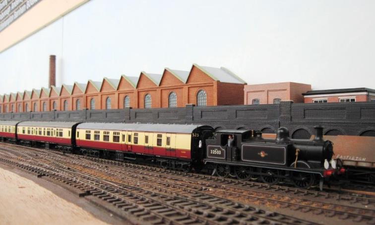
Against the backdrop of the single-story
agricultural-based works, E4-class no.32503 hauls BR(S) CLC-liveried Mk1 3
Cor set no.525 on a Down train. |
|
Time |
Up Departures |
Time |
Down Departures |
|
xx.02 |
Victoria calling at: Dorking North Fast train from Southampton Central formed two no. 3-car loco-hauled
sets (Platform 2) Some of these services additionally include a restaurant car or
Pullman dining car. |
xx.03 |
Guildford calling at: Cranleigh Stopping train starting here formed rail motor (pull-push) else 2 LAV
set (Platform 4 Down Bay) In later years this service terminated at
Guildford. |
|
xx.12 |
Arrival from Bordon. Terminating here formed rail motor (pull-push) else 2 LAV set (arr Platform1 shunts to Platform 4 Down Bay) |
xx.14 |
Portsmouth Harbour calling at: Loxwood Semi-fast train (headcode 50) formed three no. 2-car emus
(Platform3) |
|
xx:22 |
Victoria calling at: Dorking North Semi-fast train (headcode 50) from Portsmouth Harbour formed three no.
2-car emus |
xx.28 |
Arrival from London
Bridge Suburban stopping train (headcode 29) terminating here formed 4-car
emu(s) having detached 4-cars at Dorking North (Platform 1). |
|
xx.34 |
Passing time Dorking North Fast train (headcode 46) from Portsmouth Harbour formed two no. 4-car
emus (Platform 2) |
xx.34 |
Reading (Southern) calling at: Cranleigh From Brighton via Horsham formed 3-car loco-hauled set. |
|
xx.42 |
London Bridge calling at: Forest Green Suburban stopping train (headcode 29) starting here formed 4-car
emu(s) attaching at Dorking North to form 8-car to London Bridge. (Platform
1) |
xx.43 |
Passing time Havant Fast train (headcode 46) formed two no. 4-car emus |
|
xx.47 |
Brighton calling at: Oakwoodhill Warnham Horsham West Grinstead Partridge Green Henfield Steyning Bramber Shoreham-by-Sea Hove Semi-fast train from Reading South via Guildford & Cranleigh
formed of 3-car loco-hauled set (Platform 1). |
xx.54 |
Southampton Central calling at Midhurst Fast train formed two no. 3-car loco-hauled sets. Some of these services additionally include a restaurant car or
Pullman dining car. |
Electric
Train Headcodes
Southern Electric
services carry a two-digit route headcode. Older electric units used stencils
to display their headcodes and as each motorman’s cab only carried one
set of number stencils, headcodes using duplicate numbers (such as 11 or 22)
were not used until roller blind headcodes came into use; even then they were
initially allocated to diesel-operated services.
Ewhurst Green’s
services operated over both Central and South Western Divisions (they also ran
close to South Eastern Division services at Victoria and London Bridge).
Accordingly, the designated headcodes needed to take this into account.
|
Code |
Route |
Notes |
|
2 |
Dorking to Ewhurst
Green |
Morning peak-hour |
|
4 |
Waterloo to Portsmouth
Harbour via Bookham* |
*else Ewhurst Green |
|
16 |
Holborn Viaduct to
Ewhurst Green |
Rush hour service |
|
18 |
Victoria to Portsmouth
Harbour (stopping via Mitcham Junction) |
(Victoria Littlehampton services renumbered 28 ) |
|
27 |
London Bridge to
Ewhurst Green (via West Croydon) |
Code not used on SWD. |
|
29 |
London Bridge to
Ewhurst Green (via Mitcham Junction) |
Code not used on SWD. |
|
46 |
Victoria to Portsmouth
Harbour (fast via Mitcham Junction) |
(Victoria Bognor Regis |
|
50 |
Victoria to Portsmouth
Harbour (semi-fast via Mitcham Junction) |
(Victoria Littlehampton services renumbered 70 ) |
|
74 |
Waterloo to Ewhurst
Green |
No conflict with CD or SWD. |
|
82 |
Victoria to Portsmouth
& Southsea (via Mitcham Junction) |
(Victoria to Crystal Palace services renumbered 66) |
Chapter Seven

|
In the autumn sunshine
the Crimson Lake liveried pull-push set |

External Passengers & People
For the
more-distant sections of the layout a few of Bachmann’s 4mm figures have
been used as these were simple and straightforward to fit. However, for the
station’s passengers and staff (in both the coal and goods yards) higher
a standard of professionally painted figures were procured from by Pete Goss.
Having rapidly
exhausted much of Pete’s excellent range of figures (including
differently painted duplicates to swell numbers), a further preparation and
painting order was placed comprising unpainted figures (mainly) from Dart
Castings and the now sadly defunct Aiden Campbell 4mm range (pleased
I’d the foresight to invest in these).
|
|
|
|
Selection of standing passengers |
Express Dairies milkman & crates |

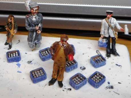
Pete’s work
starts with trimming
off all those parts not required (much from the casting process), thence
drilling, pinning and assembling figures prior to placement in wooden holed
timber jigs. This enables the figures to be sprayed with etch primer prior to
painting with acrylic paint. Ultimately Pete provided a large number of figures
all with a significant consistency of appearance.
|
Mk1 CK fitted with Preiser’s
seated people. |
Internal Passengers
Arguably one of the
most import features of a model railway are the passengers and people; these
bringing the scene alive . Passengers within trains are reasonably
straightforward and even with 4mm (OO) the use of 3.5mm (HO) seated people is
ideal as these sit well within the often overscale interiors.
Figures used from Preiser’s
unpainted range includes cat. no.16328 (120 seated figures) cat. no.16349 (36
seated figures for buses etc), cat. no. 16358 (72 seated figures) while
Faller’s equivalent is cat. no.1485 (again 72 figures per pack). When
search for these ‘seated people’ tends to display more
results than ‘seated passengers’.
Just under 3000
figures are now being painted by my son using Army Painter Speedpaint on a light grey primed surface (he will of course be well rewarded
for his hard work). This may sound a lot but when spread out across all the
coaches only averages around two per compartment!
Loading Gauge
Although the LBSCR loading gauge was reasonably
generous we will assume this route was out-gauged (along with Three Bridges -
Redhill- Reading) during the Great War to provide the LSWR with an alternative
route to Havant via Raynes Park and Epsom. Accordingly, with fewer curves and
gradients than the Pompey Direct, this route offered a viable route to
Southampton and Bournemouth; particularly for diversionary workings if (say)
Winchester St. Denys or Woking was blocked.
Diversity of Rolling Stock
Ewhurst Green (Surrey) could also provide a rare
opportunity outside of London for the mixing of rolling stock of the Southern
Region’s three divisions (SED, CED & SWD); some SED services coming
down from Reading.
Accordingly, coaching stock could include SED
Birdcage sets on services from Reading. Before the Second World War ex. LSWR
Gate-Stock operated to Guildford and it is not improbable that other ex. LSWR
coaches would have reached Ewhurst Green (either from Guildford or Waterloo to
Cranleigh via Dorking). During the period modelled, Maunsell and Bulleid 59
multi-door 3 COR sets were used in the area along with other Pull-Push stock
including the Maunsell pull-push conversion sets.
The main line would have used electric suburban
units (terminating) and lavatory stock down to the coast but needed locomotive
hauled sets to travel west from Farlington Junction to Fareham and beyond.
The layout easily manages twelve-car non-stop
trains on the main line (for example Portsmouth Harbour twelve-car train of 4
BEP /4 CEP /2 HAP units) thirteen cars if an MLV is present. However, visually
eight coaches maximum appears to visually work best whether this be an electric
train or a locomotive hauling (say) two number BR(S) three-car coach sets
(perhaps with vans) or longer sets with a buffet /Pullman car inserted.
In order to achieve these services, the two main
line through platforms (2 & 3) would be able to handle twelve-car trains
although the actual platforms are only ten-coaches long; most trains usually
being eight-car 2 BIL /2 HAL or 4 CEP /2 HAP formations. Used mainly for
departing branch services, the non-electrified Down Bay (platform 4)
comfortably handles six-coach lengths; branch trains being shunter across to
clear platform 1 and provide a convenient interchange between platforms 3 and
4.
Electric Trains
4 SUB (inc. augmented 3 Car Motor Units), 2 NOL,
and 2/4 EPB (BR & SR types) units all operate the four and eight-car
stopping services up to London Bridge and several peak-hour suburban electric
services ran into Waterloo from Ewhurst Green, joining the South Western main
line at Raynes Park.
The Portsmouth Harbour services utilise 4 COR /4
CEP /2 HAP units on the fast (non-stop) services with 2 BIL /2 HAL combinations
on the semi-fasts with 4 BEP units providing peak-hour catering facilities.
|
N-class no.31848 in its mid-fifties |
Locomotive-hauled Trains
Fareham and Southampton services variously use
Maunsell sets, Bulleid 59’ multidoor stock, Bulleid 64’ stock and
BR Mk1 corridor stock; a few of these services included dining facilities.
Locomotive-hauled set no.904 was redeployed from
the Oxted lines to operate one of the two peak-hour services into London Bridge
(routed via Dorking North and Peckham Rye). Weekdays this set would be kept
overnight at Ewhurst Green (along with an eight-car suburban emu formation)
running ecs to Guildford (reverse) to provide both Bramley & Wonersh and
Cranleigh with a semi-fast peak-hour train into London Bridge. After the
Saturday morning Up peak-hour train (at that time Saturday mornings were
part of the working week) the set was kept at Eardley sidings before
arriving back ecs on the Sunday afternoon. Originally six-coaches, set no.904
had its SECR TL replaced by two green Bulleid CK coaches so then comprised
BS-S-S-C-CK-CK-BS in Crimson Lake (these Mk1 coaches were repainted BR(S) Green
in 1958).
Reading Services
In terms of Reading services ex.SECR
Birdcage and ex.SR Maunsell sets were used along with Mk1 non-corridor 3-coach
sets displaced from Exmouth Junction services. Both the Reading and Guildford
services also used 2-coach rail motor (pull-push) sets; some strengthened with
an additional air-controlled coach.
However, all were now under threat from the new 2H
Hastings and 2H /3H Hampshire units on services through to Reading. By the time
the full Reading Tonbridge ‘3R’ service was implemented in on 6th
September 1965 the Reading to Ewhurst Green services had significantly reduced
to mostly a Guildford to Ewhurst Green shuttle.
Goodwood Race Days
Race days at Goodwood (served by Singleton station)
would see special trains down from London to Singleton with strengthened
connecting services from /to Reading. Often a spare Dover boat train formation
from Stewart’s Lane was employed (as happened on the Newhaven services);
often with the MLV still attached so as not to waste time detaching /attaching
(ironically the MLV was sometimes detached at Newhaven and used as a return ‘taxi’
to the driver’s depot at Seaford). Perhaps these spare boat-train
sets also operated several special-day services to Portsmouth or a specific
daytime service?
Still looking for a robust reason for including a
TLV yes, I know the MLVs & TLVs essentially operated on SED and the
latter is outside my era, but in 1968 number TLV S68203 did enter service in
lined maroon livery.
Similarly looking for a
reason to operate a 10 BEL formation,
perhaps on a Race-special to Goodwood else a Special to Portsmouth Harbour?
Chapter Eight

|
Ronuk of Portslade produced polish and had a fleet of
two tanker wagons, these were expertly weathered by TMC from an original
photograph. Ronuk appeared to have two 3,500 gallons railway
tankers numbered 34 & 38; these carried white spirit between Esso at
Fawley and Portslade. Producing polish, Portslade’s Ronuk
factory was established in 1902 & rail-served from c.1920; the name Ronuk being an Anglicised form of ronak (Kurdish clear ) /ronaq (Urdu lustre ) /raunaq
(Persian). In the late
1950’s Newton, Chambers & Co. acquired Ronuk,
the Portslade factory was closed and production moved to
Sheffield. However, the Ronuk-company
brand-names Colton & Ronseal still survive. |
I’ve never worked out why Ewhurst Green was a
useful location for freight although is saw a degree of goods and container
traffic. This line could also have remained useful route for through freight
between places such as Temple Mills (ER) and Holloway Yards (ER), Hoo Junction
(SED), Norwood Yard (CED) and Southampton (SWD) as well as North Camp,
Chichester and Shoreham (CED) along the West Coastway
(via Lavant). Local freight facilities are provided at Ewhurst Green, although
their use is on the decline.
|
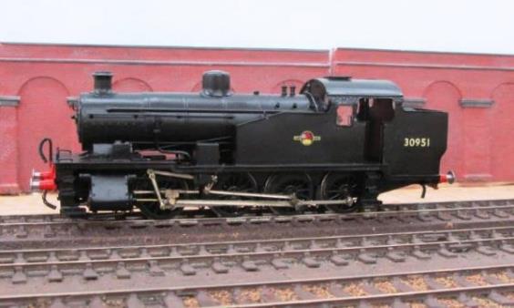
Z-class no.30951 on shunting duty. |
Dunsfold’s Airfield
Limited traffic is envisaged to service
Dunsfold’s wartime-built airfield (in particular delivering components
and aviation spirit) to the Hawker Aircraft Company. Little is written about
the line serving Dunsfold airfield (from near to Cranleigh). From this siding
the curving line crossed the wartime-built Alfold by-pass and into the
airfield. Given the nature of the spur and the reduction in post-war freight
traffic, trainloads were inevitable short with suitable motive power limited to
short-wheelbase locomotives (my excuse for locomotives such as a USA /B4 tank
engines).
Accordingly, (on the days freight services ran)
there were at most two trips down to the airfield; the early mornings saw
locomotive and tank wagon with the locomotive returning hauling vans. In the
evening loaded vans were taken down and the locomotive returned with the empty
tank wagon.
|
Visiting S15
no.30842 hauls a fitted freight through Ewhurst Green during the 4th
September 2021 running session. |
Facilities
Apart from the needs of the yard’s shunting
locomotives (coal stage), facilities were basic with just several water columns
at the station. Any locomotives that would need turning would have to trip
through to either Guildford or Horsham shed. It isn’t really plausible
that the Deepdene Holmwood spur (closed 1900 /reopened 1941-47) may have been
retained to create a loop for freight traffic in order to reduce the need for
(say) locomotive turning upon termination (from the Guildford direction).
Chapter Nine

|
Visiting stock
regularly gets to run on Ewhurst Green and here a pair of Blue /Grey 2 COM
units lead a plain Blue 2 EPB on the Up Main. The 2 COM units
nos.6213 & 6259 were the last pair to survive in service on 13th June
1995 with 6259 being the one chosen for preservation (reverting back to
5759). Although Bachmann made unit no.6238 in this livery it did not carry a
2 COM red cantrail band as its compartments had previously been opened out
into a saloon at Slade Green in April 1984. On the rear is
Blue 2 EPB unit 5764 which was facelifted to 6264 on 19th December 1994.
No.5764 ran in blue livery from 25th July 1969 and was outshopped in Blue
/Grey livery in February 1984. MLV no.68009 quietly sits between turns in the
Down headshunt. |
9.
Ewhurst Green after my Modelling Period
In just a few years the route was reduced to a basic half-hourly service to Portsmouth Harbour; stations such as Cocking and Stoughton & Walderton being closed with others (for example) Singleton being reduced to rush-hour and race days only.
The line through Ewhurst Green would have probably
hastened the 1955 closures of Midhurst to Petersfield and Pulborough (serving
only Petworth) to pre-war (WW1), the route to Guildford closed in 1965 along
with the Midhurst to Chichester passenger services (which had survived because the sturdier embankment near Cocking
hadn’t collapsed).
The through Fareham /Southampton services were
gone; even the London Bridge service was reduced to just two trains each
morning /evening peak-hour as an extension from Dorking North (these now being
the only services to call at Forest Green). The only freight traffic left was
through trains; this still being a useful route to Portsmouth and Southampton
taking the pressure of the curving steeply graded Pompey-direct and the SW main
line.
Did this electrified line succumb to closure or is
it simply difficult to find in timetables?
Chapter
Ten

|
London end of the layout after construction |
Layout sizes can sometimes be physical too small in
terms of the station being modelled and a degree of compression is (usually)
inevitable. So, I’d considered basing my model on stations such as
Groombridge /Barnham /Ford /Horsted Keynes /Lingfield /Dorking North (etc).
That is two through platforms (2 & 3) and an Up Passenger Loop (platform
1). Alongside the Up Passenger Loop would be freight reception road similar to
Redhill - plus a shunting road in the yard.
On the Down side (country-end) was a short 6-coach bay (platform 4) and adjacent dock served from a headshunt. With no main signalled route into the bay, it was only ever intended to provide a cross-platform interchange to Cranleigh off trains arriving from London.
Barnham, Ford, Groombridge and Horsted Keynes
stations had a similar layout located on or close to junctions (which can lead
to much operational interest). Essentially the mainline will operate as Up and
Down circuits (with the possible splitting /joining of electric trains in the
through platforms). However, it is the branch (with its through and terminating
services) that will see the core operational interest on the layout.
Essentially platforms 2 & 3 would see the
through services (both Branch and Main) with suburban services from London and
Branch services terminating in platform 1. Also arriving in platform 1, local
Branch services would then shunt across to platform 4 to restart their journey
(similar operational moves took place at
locations such as Oxted and Eridge).
It was decided to place the main station building
towards the rear of the baseboards on the Down side. Besides placing the
platform-side of the building on view, this also left uninterrupted space along
the front of the baseboards for the Up Passenger (platform) Loop (where branch
trains would be terminating) and the goods reception road and sidings (i.e. all
within easy reach). Accordingly, the model’s operator looks south-east
towards the station.
This station concept provided the basis of the
baseboard design.
Enlargement of the Station
However, it doesn’t end there as the history
of the station can be seen in the model; many stations undergoing change across
the decades. When the railway was originally, built Ewhurst Green station was
double-tracked with two four-coach-long brick-built platforms, a Down-side dock
along with a larger Up-side goods yard.
Electrification would have led to enlargement of
the station to accommodate the terminating of 8-car suburban electric services
plus now a greater need for interchange facilities onto the Cranleigh branch.
This would have needed an Up Passenger Platform Loop and Down Bay (for
departing Cranleigh branch trains).
So, the mainline platforms were lengthened and a
6-coach Down Bay created at the expense of most of the small Downside goods
yard. Without a costly rebuild (plus additional /difficult land-take beyond) Somersbury Lane overbridge created a limitation in respect
of the headshunt for shunting back into the remaining goods siding and dock.
With the factory standing atop the cutting, in order to enable a headshunt to
be taken up to Somersbury Lane overbridge, this
cutting had to be dug out and replaced with a retaining wall.
The Up Platform was widened to meet a new Up
Passenger (platform) Loop capable of holding an 8-car electric train and the
London-end yard entry amended accordingly. The Up Passenger (platform) Loop
stopped short of the Up-side subway buildings as only an 8-car length was
required. South of the new Platform Loop an 8-car electric siding was created
along with an equivalent length carriage siding.
These new works was undertaken using concrete harp
& slab construction technique as supplied by the Southern’s Exmouth
Junction concrete plant. Re-signalling took place and a few years later the
main signal-box was replaced; the ex. LBSCR London-end box remaining as it
oversaw the level-crossing.

|
With tracklaying in progress and the retaining
wall planned Ivatt no.41250 passes pull-push set 610 (being propelled by
no.31518). The final retaining wall (Bachmann) differs from the (Hornby) wall
here and single story industrial buildings were more in keeping than the
three floor building. |
11. Storage Loops & Fiddle Yard Layout
Storage loops and fiddle yards can be a significant
part of a model railway for these represent the rest of the UK network enabling
trains to leave Ewhurst Green returning later in the day.
Trains entering the storage loops are kept there
until needed again; some will set back to Ewhurst Green whilst others will move
along the storage loop until it is their time to reappear. Some loop-lines each
store just two long trains whilst others can store six shorter trains.
For the Cranleigh branch the fiddle yard comprises
four tracks nearest the operator, and these involve reassembly of formations
including a simple changing end of locomotives. The Cranleigh branch also has
two dedicated storage loops capable of holding ten trains on each.
The storage loops and fiddle yard have six distinct
sections:
|
(1) |
Down Main storage loops (total 5 no. + 4
additional loops), |
|
(2) |
Up Main storage loops (total 5 no. + 4 additional
loops), |
|
(3) |
Up and Down Branch storage loops (one each), |
|
(4) |
Branch Terminating (two 6-car tracks), |
|
(5) |
Branch Terminating (two 5-car tracks) & |
|
(6) |
Locomotive depot. |
These are all designed to permit realistic
operation of the station with a combination of through and terminating
services.
|
(1) |
Down Main |
The Down Main storage loops comprise total nine
loops; five loops numbered 1, 2, 3, 4 & 5 to start with then two further
loops each off roads 1 and 5 (numbered 1a, 1b, 5a & 5b). These are capable of taking full-length trains
although some are electrically subdivided to accommodate eight and six-car
(equivalent) lengths (say eight-car emu formation or locomotive plus two
three-sets and luggage van or buffet car. |
|
(2) |
Up Main |
The Up Main storage loops (6, 7, 8, 9 & 10
plus 6a, 6b, 10a & 10b) replicates the Down Main albeit for travel in the
opposite (anti-clockwise) direction. |
|
(3) |
Up and Down Branch storage loops |
The Up and Down Branch storage loops (11 &
12) are just double track split into sections each being five-car
(equivalent) lengths (say locomotive, three-car set and luggage van). Alternatively, two loops together could
accommodate a train of ten-car lengths. |
|
(4) |
Branch Terminating |
Branch Terminating loops 13 & 14 (6-car fiddle yard) accommodate five
number trains up to six-car (equivalent) lengths. Although intended to
terminate /return stock into the south end of Ewhurst Green it is capable of
terminating trains from the north end of Ewhurst Green. It also includes a four-car length loop for
electric trains terminating from the north end of Ewhurst Green. |
|
(5) |
Branch Terminating |
Branch Terminating loops 15 & 16 (5-car fiddle yard) accommodate six
number trains up to five-car (equivalent) lengths terminating /returning
stock into the south end of Ewhurst Green. It also has two storage sidings (16a & 16b)
of three-car (equivalent) lengths for the storage of Pull-Push formations or
diesel electric multiple units. |
|
(6) |
Locomotive Depot |
Accessed off roads 13 to 16, the Locomotive Depot
comprises a non-scenic turntable serving both of the Branch Terminating
fiddle yards with storage for locomotives. |
More on this later.
Chapter Twelve

|
With HA E5001 on the test circuit, USA tank
no.30069 tries the (then) |
The layout is housed in a dedicated purpose-built
and well-insulated studio; the temperature running at a constant temperature
from an inverter proving air-con /heating (well worth the investment and
surprisingly cheap to run).
Baseboard Height
The layout’s baseboard was built at a height
of 52” using 3” by 2” timber with the top made from 12mm high-quality
exterior plywood (as supplied by an excellent local timber merchant). In other
words, strong enough to rest or even sit on!
After much musing with good friend Ian, this figure
of 52” high had been derived from a number of factors; the main one being
able to look at the railway from a more realistic sideways viewpoint rather
than looking down from a great height onto train roofs. Ian uses a similar
height on both his Oxted and Redhill P4 layouts. It is also a convenient height
to duck-under when the drop-down door flap is up in use and trains are being
run.
|
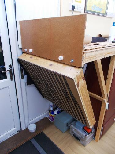
Prior to fitting of the layout’s green
facias, the fold-down flap in front of one pair of external doors. The end board is to protect rolling stock when
the flap is folded down out-of-use. The hardwood cill underneath the cats water bowl protects two 37-way
cables below. |
The height of 52” still places the rear of
the layout within practical reach whilst enabling tasks such as wiring and the
fitting of turnout motors (etc) to be undertaken from the relative comfort of a
swivel chair (until such time that I can
obtain a chaise-longue on raised legs with castors).
Furthermore, this height provides sufficient
clearance when leaving the trackroom with the flap
closed (trains running).
|
Terry undertaking construction |
Baseboard Width
Nominally 30” wide (the furthest one can
realistically reach and work), each corner has a triangular pop-up hole where
one can stand up to gain access.
Baseboard construction was undertaken by friend
Terry (a.k.a. the Rigger) who flew in from his mountain retreat in the Algarve
to construct the baseboards the lure of tea, biscuits and Cornflakes being
simply too irresistible!
Having constructed the boards for his own layout
thence Ian Sneyd’s P4 Redhill 1938, Terry has since gone on to construct a
friend’s baseboards for his 4mm take on the interesting arrangements at
Inverness.
Ewhurst Green’s fiddle yard boards were built
in March 2015 and the station boards completed October 2015. During the latter
visit the simple test circuit was also installed.

|
As part of his inspection, Moser patiently
undertook the first static load test of the baseboard |

|
Not to be outdone by Moser, Terry undertook the
same static load test |
However, on the station side the 30”
baseboards widen to around 50” at each end, which would ordinarily leave
the rear of the layout out of reach. The solution was simple in the form of two
drop-down sections being provided (similar to the entrance door flap) to
provide access-reach; it is this flap that is demonstrated in the static load
testing photographs rather than just the permanent (fixed) baseboard!
In order to
protect the scenery on these flaps their design enables them to be swung
through 180o and secured upside down out of the way by means of a
fixed cord operated on pulleys. Track only passes onto the boards at the inner
ends and at 90o so there wasn’t to be any skewed rail joints.
Once
secured up into place by a simple sprung (brass window) latch at the far end
the inner end is drawn tightly into alignment by use of a brass sash window
screw latch; this system also being utilised on the drop-down entrance flap.
A credit to Terry’s engineering skill; the
baseboard top-framing is shimmed to provide a maximum deviation of less than
2mm between opposite ends of the layout. This top framing was also designed so
as not to interfere with the future positioning of turnout motors and the
positioning of the legs to optimise storage; the legs being screwed to the
(insulated) floor.
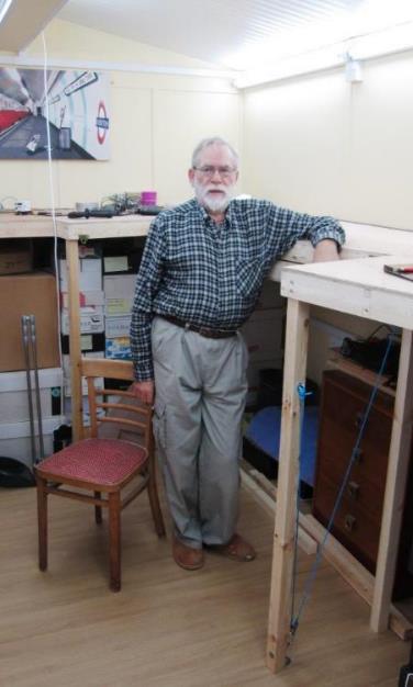
|
After the static load tests were completed, Terry
demonstrates how this section of baseboard folds right back underneath in
order to provide access to the rear of the baseboards. |

|
Country end of the layout’s boards with its
own (identical) folding section; pulley & cord are just visible between
baseboard and floor. |
In 2017 end-protection boards were built for the
drop-down entrance flap (using 9mm plywood recovered from my former layout).
Not only do these boards protect the rail ends at the doorway, but they also
prevent rolling stock from inadvertently descending into the abyss!
Across Easter 2018 further baseboard work took
place in the form of the green painted baseboard edging; besides providing a
neat appearance it also prevents anything falling off!
Chapter Thirteen

|
With 3mm cork and centreline pins in place on the
Up Line the |
Modelling in 4mm, I have always used 00 although
have thought long and hard about EM or P4. With so much available in P4 these
days I could see little reason to change to EM even though for the majority of
my rolling stock it would have been relatively simple to ease out the
back-to-backs of their finescale wheels. P4 looks superb except the tolerances
are so fine much precision is required and this could prove tricky on a large,
fixed layout (even the 00 track has needed adjustment in-situ).
However, the change to either gauge would
necessitate a significant amount of additional work including starting again
with all the trackwork instead of component-recovery from my previous layout.
Now with failing eyesight, this was the correct decision.
Even with 00 the tolerances at the wheel /rail interface
are still fine and both track and wheels need adjustment. Certainly, using
old-style copper-clad turnouts means this can be undertaken with a
soldering-iron!
Storage loops & Fiddle yard Trackwork
The minimum radius used on non-scenic sections is
36” and for the fiddle yard Peco code 75 ‘HO’
track is employed being cheap, practical, of standard dimensions and simply
laid onto 1.5mm cork. Unfortunately, the 36” minimum precluded the use of
Peco single /double slips in the fiddle yard which appear to be only
30” radius.
The mainline storage loops are set for differing
train lengths - some can hold six-number 4-car electric units; other hold a
thirteen-car boat-train set.
The branch fiddle yard is designed for five and
six-car equivalent lengths. For example, a five-car length provides for
locomotive, van and three-car coaching set. Longer trains can be accommodated
through the doubling up on bays. It comprises Up and Down Branch (through lines
for trains undertaking a circuit) thence four sets of roads for terminating
services.
Scenic Trackwork
Both Exactoscale (C&L
Finescale Modelling Ltd) and SMP track is employed in the scenic
sections being laid on 3mm cork and paired to Marcway
turnouts. However, although I had a small existing stock of SMP track
left over from Apothecary Street I decided to move forward using Exactoscale as the track has a considerable edge
including crisper sleeper mouldings. Accordingly, the remaining stock of SMP
track was used up on the less visible sections of the layout.
The new Peco 4mm bullhead track was
examined and whilst its sleeper sizes /spacing look good the overall rail
/sleeper height differs from Exactoscale /
SMP /Marcway track (it also
differs from Peco code 75 track). With limited availability it was
not considered for use.
There is a small transition in height between the
scenic track (Exactoscale ) and fiddle
yard (Peco code 75 track); this being achieved through the use of
graduated shims made from card and the different thickness of cork underlay
(1.5mm and 3mm).
The choice of Marcway
turnouts was a relatively simple one; for although they are of
copper-clad construction (which many would suggest is dated, even crude by
today’s standards) from a distance they still look reasonable and all of
Apothecary Street’s Marcway turnouts
were recovered for possible reuse; these being stripped, cleaned and repainted.
In addition, Marcway turnouts are simple
to repair and adjust in-situ. On an operational model railway (on fixed boards)
sheer practicality in terms of ongoing maintenance has to be a significant (if
not an over-riding) consideration.
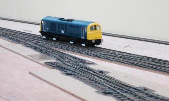
|
With the S&C now laid, part ballasted,
switches motored and wired it is tested with an HA (71 012). |
The track centrelines of Ewhurst Green were set out
by means of both chalk-line and laser technology with the centrelines marked
then delineated using track pins. Mounted on 3mm cork the scenic track is held
in place before light gluing (if needed), painting thence ballasting the
four-foot to fully secure it. The paint (Railmatch
Sleeper Grime) actually makes an excellent adhesive.
Rather than the 50mm used by (say) Peco the
track centres are set at 45mm in order to give a scale six-foot (although the
distance measured between adjacent running rails is actually slightly wider due
to the 16.5mm 00 track gauge). However, to enable sufficient clearance between
passing trains on curves tighter than five feet radius, the six-foot dimension
is increased up to 50mm; this being used on the layout’s three-foot
minimum radius curves. The storage loops and fiddle yard simply use the
standard 50mm spacing throughout.

|
Looking south towards the double junction and the
line to Cranleigh (curves away just to the left of and behind the
sub-station) from above the Up Main Line platform. The correct six-foot dimension between Up and
Down Main lines is noticeable in this photograph as is the correct conductor
rail offset whilst allowing for the 16.5mm gauge track. |
Switches and Crossings
Where needed, a number of the scenic turnouts were
carefully rebuilt to incorporate the required long timbers therein;
particularly required as a scale six-foot dimension had been adopted. This
means 45mm centres instead of the standard 50mm more usually adopted by many
modellers and Peco (a necessary compromise by manufacturers to
accommodate the sharp radii without varying this distance).
Turnout Motors
Tortoise turnout motors were used
throughout, albeit with 0.9mm wire drive for the mechanically stiffer
switchblades of the Marcway turnouts. Even
then this wire size is only just strong enough for the short switches on the
double slips; each double slip requiring four motors one motor per pair of
switchblades!
Not only did this choice of turnout motor enable
standardisation across the layout (each motor was fitted with a lead and plug
of standard configuration) the two sets of contacts thereon enabled switching:
one set being used for the polarity of each turnout’s common crossings.
At the last count ninety-nine Tortoise motors were in use – a recount is
needed!
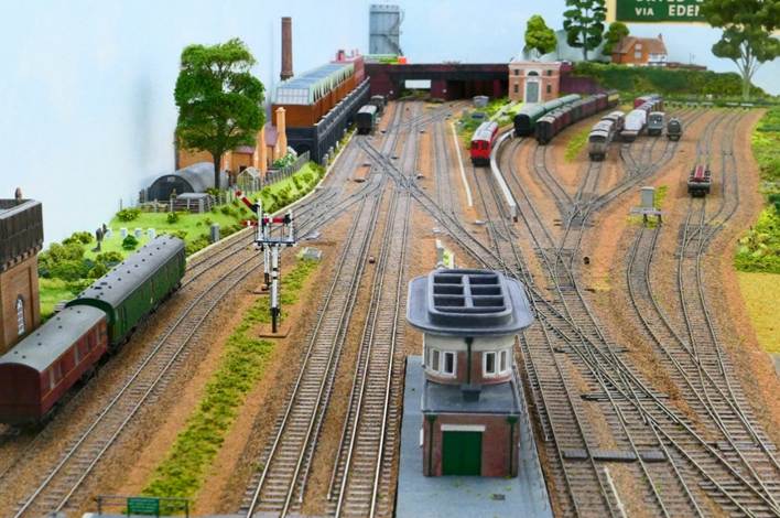
|
London-end - Up Line (plat. 2) is complete with the Down Line (plat.
3) awaiting removal of the test circuit. In the foreground is the Up Loop
No.1, Up Passenger Loop (platform 1) thence the Up and Down Main lines. Note the use of
staggered baseboard joints to reduce the amount of bracing required underneath. |
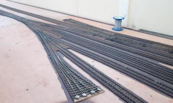
|
Country-end S&C with entry into five goods sidings (middle
foreground), two carriage sidings, Up reversible, Up and Down Main thence the
entry into the Down Bay /headshunt (rear). |
Some of the Marcway trackwork
does need fine adjustment to enable fault-free running; particularly a few
tight-to-gauge areas in the middle of the slips /double slips. This included
tightening of the checkrails. With copper-clad track this is a relatively
straightforward exercise using a Vernier gauge, fine soldering iron and
patience. It is well worth spending time on doing this as the results are very
effective.
|
Buffer stops at Horsham - left BR type &
right LBSCR (three-bolt with LSWR beam but laid on two-bolt track) |
Buffer Stops
Lanarkshire Model Supplies produce an excellent LBSCR buffer stop kit and one of these was the first buffer stop to be
installed on the Down Headshunt. Peco produce an equivalent BR buffer stop kit and whilst arguably rarer on the Southern Region
in the Ewhurst Green period, were assessed to be used in vulnerable location as
they clip onto the railhead and are potentially simpler to replace if damaged.
However, the Peco turnouts were found to be far too
delicate and flimsy so all were discarded in favour of a small varied selection
from Lanarkshire Model Supplies whose excellent buffer stops are simply a joy
to fabricate.
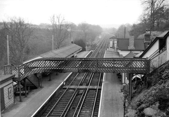
|
Third rail electrified track
(towards London) at Balcombe station on 12th March 1961 (Up
direction). Ben Brooksbank
(CC-by-SA/2.0) |
Conductor Rails
Getting the conductor rails right is important
although there are certain practicalities that need to be considered,
particularly with regard to clearances to trains and maintenance.
Peco produce conductor rail pots for use with code 60 rail. Whilst their code 60 rail isn’t quite the right profile for (say 100lb/yd) conductor rail
on a large working layout it is much easier to use these products that opt for
something that it more authentic. Ultimately when standing back at a distance,
the visual effect is achieved..
With 4mm /OO SMP /Exactoscale
track the sleeper lengths are shortened to 8’ instead of 8’
6” which can lead to issues with placement of the conductor rail and
visually make the distance between running rail and conductor rail look to be
greater that it really is.
Yes, the conductor rail can be positioned at a scaled
5.2mm from the running edge for the shorter sleepers except some models use the
correct bogie widths for (say) axle boxes (etc) on their models and these can
foul the 5.2mm conductor rail. So, on Ewhurst Green the centreline of the
conductor rail is just under 6.5mm from the running edge (the reasonably
correct distance from the track centreline). Even then the shoes on Bachmann
Mk1 4 BEP /4CEP /2 HAP /2 EPB stock sit inside the conductor rail whilst those
on Hornby’s 2 BIL /2 HAL stock on its outside. In terms of the latter
units, gentle filing of the inside of the shoes is required.
The Peco conductor rail pots enable the conductor rail to be removable (for
maintenance) through being an interference fit into the holes drilled in the
sleeper ends. With my failing eyesight, a friend has spent many hours hunched
over my baseboard drilling out holes in the sleeper-ends and fitting sections
of con-rail whilst I frantically struggle to catch up on replacing the 0.75mm
drills that frequently get broken in the process.
Once fitted, the conductor rail is eased out and
(without moving the conductor rail pots), spray-painted in primer before
painting in sleeper grime. On railways of this period, the conductor rail pots
became dirty relatively quickly, turning brown in the process.

|
Side-ramp in Horsham station’s sidings. |
Side-ramps
Side-ramps are modelled (albeit few in number);
these being used where the conductor rail is present adjacent to a
turnout’s switches to enable the train’s collector shoes to join or
(smoothly) leave the conductor rail at turnouts albeit with a 20mph speed
restriction onto a side-ramp. Located adjacent to the switch-tips, side-ramps
were employed where non-electrified lines joined electrified lines lest an
electric multiple unit was being hauled dead with its shoes hanging down.
|
Two side-ramps in front of Lewes signal box. |
Most of the Southern Region was shoe-cleared for
hauling an electric multiple unit (even the Weymouth Tramway was assessed
during my stint in the Southern Region’s RA&G department but not
cleared for possible class 442 haulage because of the road surface
profile). However, side-ramps are frequently omitted by modellers. In terms
of the UK’s two standard-gauge fourth-rail electrified systems, LUL has a
limited number of side-ramps; the MoD has none.
|
Protection-boarded conductor rails including
adjacent to the carriage walkways at Horsham station. |
Conductor Rail Protection Boards
At a number of locations conductor rail protection
boards would have been used and these are produced by several manufacturers.
However, their supports are fit under the Peco conductor rail insulator ( pots
) and so lift the conductor a fraction too high, sometimes leading to fouling
with the shoegear of Hornby’s electric multiple unit stock. Furthermore,
with the potential for some thirty-feet of protection boarded conductor rail,
maintaining adjustment would also be tricky and a potential a nightmare.
Conductor rail protection boarding can also be
created using rail soldered in 1/8” brass channel and at a distance it
looks the part; as a solution it is robust. However, again the shoegear of
Hornby electric multiple unit stock can foul this (Bachmann is absolutely
fine). Ultimately a decision was made to omit this protection boarding.
However, I was fortunate to have enough KS181 brass
channel left over from Apothecary Street to create boarded conductor rail in
the carriage siding where the protection boarded conductor rail noticeably sat
alongside the carriage walkway; possibly to give assess to the undersides of
each car. In recent years as part of my professional duties I ensured wherever
practicable the con-rail was placed on the side furthest from the walkway.
In the middle of the station platform there is a
boarded foot-crossing for staff; today these having long been closed at
stations as they are dangerous with a significant risk of staff being struck by
trains (staff should use the alternative route via subway or footbridge).

|
Protection-boarded conductor rails used to run
through many of the walkways at Horsham station. |
However, for the period of Ewhurst Green not only
was there a boarded foot-crossing between the platforms the live conductor rail
often passed straight through this with staff required to step over two
adjacent conductor rails in the six-foot.
|
|
|
|
Gatwick |
Redhill |
|
On the former Southern Region, the last of such
staff foot-crossings were probably those at Horsham carriage sidings, Gatwick
Airport (platform 1) and Redhill (platform 1); fortunately, all were
abolished c.2009. |
|

Chapter Fourteen
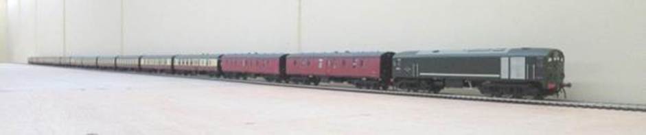
|
Using the test circuit is Terry’s The
Rigger Metro-Vick no.D5714 hauling 14 bogies with ease; this is believed to
be the only Co-Bo to operate on the BR(S) doing so from 4th to 7th
April 1960. Ewhurst Green has its own weathered D5714 (fitted with Ultrascale
wheels) for this rare visit! Unfortunately, although superb to model with, the studio’s daylight simulation lighting isn’t
particularly conducive to photography. Late in 2019 the fluorescent lamps
were replaced with daylight simulation LED units. |
(2015-2017)
Starting in 2015 a simple test track utilised the storage loop /fiddle yard area before entering the station side as a circuit (still on Peco track) albeit laid well out of the way, initially at the rear of the baseboards. Providing a circular run just over one scale mile, it had been a useful addition providing much enthusiasm as well as the centre of a number of social gatherings with East Sussex Finescale (ESF) members.
The storage loops were all laid first before scenic
station tracklaying commenced. With the scenic Up Main connected in June 2017
the test circuit was disconnected in August 2017 to allow the Country-end Down
Main to be laid; it was lifted early September 2017 to enable the London-end
Down Main to be connected.
The test circuit introduced a variety of rolling
stock onto the layout ranging from models of elderly external framed
copper-topped green kettles (of dubious parentage) through Hampshire units (an
eight-car DEMU formation has been run) to modern diesels in post-privatisation
livery. It has also seen retired Motorman Kevin’s pre-First World War
Prussian steam (very impressive) along with a modern German articulated
multiple unit!
This has given friends (who are still building
their own substantial layouts) the opportunity to let their models stretch
their legs including several that haven’t been out of their boxes for
several decades (leading to several ad-hoc overhauls) including some whose
wheelsets were incompatible with the scenic-side scale track.
The use of a friend’s DCC controller brought
sound to the layout, although limited by speaker size /technology the most
realistic versions being the Rail Exclusive /Sutton Locomotive Works (SLW)
Sulzer type-2 (class 24). Fitted with two speakers these are a long way ahead
of all other offerings; Charley Petty’s (DC Kits) class 26 /33 /3H sound
units follow with other makes further behind. However, DC Kits are now
developing high quality stereo sound units so it may be a case of watch this space!
The SLW Sulzer type-2 (class 24) set a new standard
for ready-to-run and (in my opinion) were well worth the outlay; these being a
significant advance on Bachmann’s Sulzer type-2 (class 24) model
particularly in respect of the underframe detailing; Ewhurst Green having two
Southern Region-allocated examples. Bachmann’s Sulzer type-2 (class 24)
remains a nice model; SLW have simply taken ready-to-run locomotives to a new
level and like Hornby with its Railroad range, there is space in the marketplace
for both versions.
Kernow’s Beattie Well tanks and O2 classes
run very nicely as does Model Rail’s USA tanks and Hornby’s Radial
tanks. In terms of emu stock 2 BIL /2 HAL units (including a 12-car formation)
have been run alongside visiting MLV /4 CEP stock and a blue /grey 5 BEL.
Interestingly Hornby have not sought to provide any fittings to enable a pair
of 5 BEL units to be coupled together (a small job for winter with my unit
nos.3052 & 3053). Now, if only somebody would produce a 4 LAV in r-t-r!
Ironically up to 2021 I had run very little of my
own stock!
Chapter Fifteen
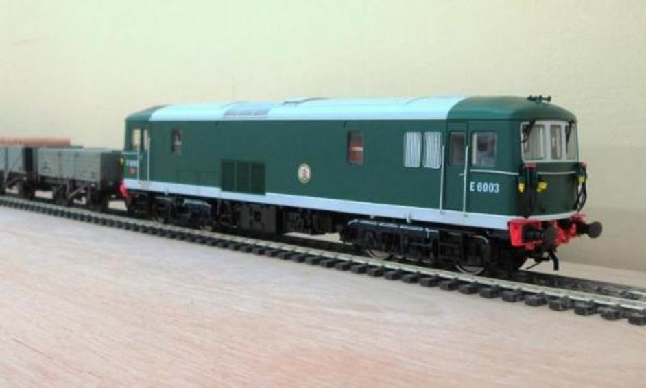
|
Dapol JA no.E6003 hauling a freight around the test
circuit. Pictured straight out of the box this is a nice model although there
is one glaring error in the form of the incorrectly parked secondman’s
wiper! |
As an old-school modeller I have not sought to
embrace DCC. However, there is no luddite here the current choice is out of
practicalities and the desire to achieve realistic railway operation in a
simple cost-effective manner; DCC only offering limited benefits in this area.
As on Apothecary Street, the control of the station will be undertaken by means
of an electric lever frame with conditional locking; I considered this would be
best achieved through the straightforward use of switches and relays.
It is regularly
stated that DCC makes layout wiring simpler. In some ways that statement is
true as it makes the modeller’s wiring much simpler; the hugely complex
wiring of the DCC controller (and possibly an operating computer) has already
been undertaken for the modeller. In other words, the starting point of your
layout construction is relative. To mis-quote Carl Sagan If you wish to make a model railway from
scratch, you must first invent the universe .
However, DCC also
introduces other complexities both in wiring and physical control along with
availability of components and obsolescence. Fault-finding with such technology
can be difficult. Furthermore, you can be tied into one manufacturer’s product
for some components and by definition their prices.
Ewhurst Green uses
a number of essentially repetitive but simple electrical circuits, each wired
the same way; it must be acknowledged that (particularly given the
layout’s length of just over a scale mile) cabling is ordered in 1.1km
lengths at a time.
Some will find this chapter complex (others may
risk falling asleep) so you can skip to next chapter.
Controlling the Layout
Apothecary Street was controlled through the
signalling by means of an electric lever frame (with conditional locking) for
the scenic section, route setting for the fiddle yard. As this obviated the
need for traditional cab-control switches and proved to be very effective I
decided to operate Ewhurst Green in the same way.
The lever frame is quite straightforward employing
high-quality former Ministry of Defence (MoD) DPDT switches mounted on robust
plastic industrial cable trunking (those switches recovered from Apothecary
Street were augmented by the lucky purchase of some more on the internet).
Apparently, each switch cost the equivalent of around 64 each new some
sixty-years ago!
In general (but not always) signal boxes have one
lever per each signal arm. However, as many of Ewhurst Green’s
multi-armed signals (such as the three home signals) are located off scene the
decision was made to use one lever per signal location; the actuating of the
correct arm (where applicable) being determined by the route set.
There is a lever for each of the three home signals
on the Up Main, Down Main and Up Branch (but not the distant signals) as
operation of these provides the track feeds. Similarly, the three equivalent
advanced starting signals enable the feeds into the storage loops /fiddle yard.
The shunting signals are non-operational. However,
the levers still need to be present; when actuated they prove the route and
provide the track feeds. Turnouts are activated is the usual way with ends
paired as per prototypical practice.
With few exceptions, each signal has its own relay
(including non-operating shunting signals). This being an electrical necessity
to electrically control the layout.
Hand points are not of course on the main lever
frame and here simple route setting switches are quietly employed at each end
of the station’s goods yard in order to switch entry into the sidings.
Storage loops and fiddle yard
In the Up & Down storage loops and Branch
storage loops and Branch fiddle yard simple route setting is used; this being
undertaken through ex.GPO type 600 relays.
As there are few instances of (say) a train
entering on the Down Line (perhaps crossing into platform 1) whilst another
departs (say from bay platform 4) it was decided that two trains would not be
running on the same circuit: apart from shunting-forward in the fiddle yards.
Every storage loop /fiddle yard track is capable of
storing more than one train on each; this being dependent upon the train length
and loops is designed to accommodate multiples of different length trains. For
example, one loop will accommodate four number 4-car emu stock (or two number
8-car units) plus an additional four units in the add-on loops (whereas another
is designed for two 10-coach trains). The long loop with add-on loops is
configured to accommodate the suburban electric services which shuttle around
the London-end of the layout between the fiddle yard and station.
The operation of the loops is simple for when the
first train out of a loop is travelling round through the station the second
train parked in the loop can be shunted-forward to create space for the arrival
of the returning first train at the rear of the loop.
The detailed operation of this is described under
the heading of Storage loops and fiddle yard Controls .
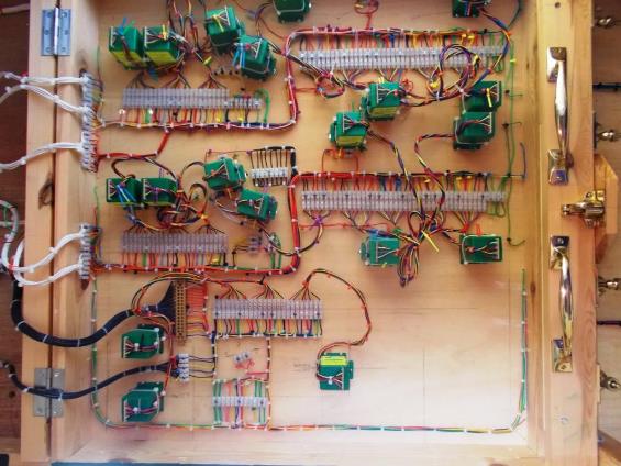
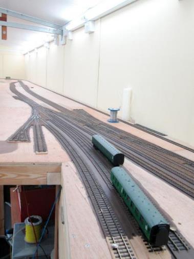
|
Country-end S&C with the main crossover
(mainly single & double slips) Left: the double junction is just visible in the
distance with locomotives on the Up Main Right: a green BSK marks the non-electrified
carriage siding; just beyond a 2 BIL DTC sits |
Conditional Locking (Signalling)
It would have been nice to have employed full
interlocking. However, I accepted that this would be unnecessarily complex for
a model railway and that conditional locking would suffice. This still requires
the correct turnouts to be set to allow the signals to be pulled off (thus
enabling the required electrical track feeds). However, instead of preventing a
conflicting route from being set conditional locking simply cuts the electrical
track feed which in turn halts the trains.
I shall not attempt to describe the circuitry
involved in detail at this stage (a basic wiring diagram is needed), save to
say that with a basic knowledge of relays the underlying principle is
ridiculously simple and highly effective; coming up with such circuitry just
needed a degree of lateral thinking. However, I am open to discussion on the
topic.
The individual circuits needed for each signal are
discussed in a subsequent chapter.

|
Much has changed since the previous photographs.
The substation has to be completed, and the carriage sidings taken to their
full eight-coach length. The track feeds and Tortoise motors are all wired in
place now awaiting the production of the relay board (underneath the layout)
to control the platform entry turnouts, trailing crossover and double
junction beyond. This section
of the layout measures some 12 . |
Track Feeds & Relays
As stated, for many years I’ve no longer
employ cab-control on my layouts; instead arranging track feeds through the
signalling with a smattering of isolating sections in the scenic sections.
Route setting is employed in the storage loops /fiddle yard with just a handful
of isolating /move-up switches controlling all tracks. Essentially it is a case
of just set the road, give a ’Proceed’ aspect on the signal and
drive the train!
Notwithstanding, the layout is being wired with the
potential to use DCC at a later date; certainly, I recognise the are benefits
from a constant 16v around the track rather than the slow starting voltages
associated with DC.
Some can find the use of relays complex. However,
whilst it requires a significant amount of wiring design and copious amounts of
relays (mostly ex. GPO aluminium-cased type 600) the circuitry involved is
essentially simplistic in terms of its repetitive design. Some might view the
task as Herculean, but really it just needs time and patience!
I like to use ex.GPO
relay carriers as it gets quite tedious if you have to build your own mounts.
However, many of these carriers (from GPO relay stations) contain ten relays:
each with two pairs of changeover contacts along with two pairs of coil feeds
resulting in ten wire-terminations per relay (eighty in total). These two pairs
of coil feeds get really useful when two separate circuits need to activate a
relay - this can be achieved without the need for selection switching.
Other relays are contained within ex.GPO metal cases up to 30 number type 600 relays at a
time. So these have to be mounted on a frame alongside a plywood panel covered
in 3amp terminal blocks (wired to each relay terminal) ready for mounting under
the layout. Thirty relays each with eight contact termination (plus two or four
coils) means 320 separate wires to be soldered and terminated. The whole unit
is then installed under the layout ready for connecting into the layout’s
circuitry!
GPO relays rarely fail but any design does need to
have a means to enable replacement without behaving like a contortionist with a
hot soldering iron in hand! Accordingly, their mounting has to provide
reasonable means of access, and this can prove challenging.
Telephone relay circuitry usually runs on 50v (I
believe some providers now use lower voltages). Whilst many of the
lower-resistance former GPO relays work well on 12v, most are run at 24v
although a number of 50v circuits using higher-resistance relays are employed;
the 50v circuits being separated isolated from the others and are clearly
identifiable. However, I would not advocate the use of 50v circuits unless you
have sufficient knowledge and experience to design and undertake this safely.
Turnout Motors
All of the Tortoise turnout motors are
powered from two-transformer sources; one side of all the turnout motors are
connected to each other. The other side goes back to the operating lever switch
(relay contacts in the storage loops /fiddle yard); this either connects to transformer
1 (positive) or transformer 2 (negative).
At the end of its movement the Tortoise turnout
motor simply enters a (designed) stall with power still present. Until the new
PSUs were put in place, I used old Hammant &
Morgan transformer-controllers (etc) for this purpose as the voltage can be
simply adjusted to an appropriate speed. In reality the need to run the motors
at a reduced voltage wasn’t necessary.
Marcway double slips each require four Tortoise motors. It is
physically possible to install all four motors on a double slip between the two
pairs of stretcher bars (motors mounted side-by-side in pairs placed
back-to-back) although this can be fiddly.

|
Tortoise motors and wiring
on the underside of the drop-down entrance flap. With hinges to the left, on
the right are the brass lift handles, holding latch thence four screw catches
used to pull the flap up into alignment. |
Turnout motors have been installed including those
on the London-end goods yard; just a couple on the south end of the goods yard
and the branch fiddle yard awaiting fitment. Standard designs of wiring
circuits are used to make work easier on both the turnout motors and associated
relays.
One pair of contacts on each Tortoise motor
switches the polarity of the common crossing on both Marcway
and Peco turnouts; this provides reliable electrical switching. On
crossovers the second pair of contacts on one of the motors makes the
electrical connection between the two tracks. Spare Tortoise motor switches are
used in the conditional locking circuitry.
Although each turnout or crossover is numbered the
Tortoise motors also carry a simple colour code using coloured cable
ties (tags). A single motor has one coloured tag, a simple two-motor crossover
has two and where three motors are employed three tags are used. Working
underneath the baseboard can be disorientating and these tags provide a rapid
but simple means of identifying motors.
Furthermore, each motor is placed in the normal
position and a bright yellow tag added to one of the made contact wires (either
yellow or blue) as a useful reminder when installing wiring. This is
particularly useful on crossovers where motors may be reversed so one end
normal is yellow wire the other end it is blue.
Each turnout number is fed through their own relay.
For example, a crossover has one number on the signal-box lever frame although
uses two motors. It is powered through one relay.
At the country-end of the station several double
slips are adjacent to a single slip. On the lever frame each have one number,
but each also have three ends with each end powered by a motor (three in total)
these being wired together to work in unison. Again, this is all powered
through one relay.
Relay panels
Where route setting is employed, the turnouts are
switched through relays. A total of four of these panels are required for the
storage loops and fiddle yard. Each relay panel comprises twenty relays
/three-amp termination blocks and two-hundred eyelets to secure the wiring!
The 12mm boards are from an 8 x4 sheet accurately
cut into nine by the timber supplier. Fixed to the board with 2BA bolts, each
relay rack can be detached lest relay replacement is required. However, each
relay was cleaned and tested before fitting and wiring; the circuits were
tested again before mounting under the layout.
These relays are former GPO type 600 dating back to
the 1950s; today it is unusual to find them with their protective aluminium
cases. Each relay has two pairs of changeover contacts and two (rather than
one) coil; this second coil proving vulnerable for switching the automated
turnouts in the middle of the storage loops.
One set of changeover contacts is used to switch
the Tortoise motors: these motors being powered from a centre-tap +12v /0v
/-12v supply from a pair of transformers. However, the GPO type 600 relay
obtain 24v of power from across the +12v /-12v connections of the paired
transformers.

|
Relay bank (nos.01-20) prior to installation. Controlling the Up and Down south-end storage
loops, these Type 600 relays are seen mounted and wired (two relays to a
column) prior to installation. The wires are secured by cable ties to brass
eyelets (just visible). Once in place the layout’s free-wring will
drop down the currently vacant columns to the connector blocks |
This relay bank is now in-situ, wired and fully
operational controlling the Up and Down Country-end main-line storage loops
along with the Up and Down Branch storage loops and fiddle yard. All the
switching contacts on all these relays are used.
In 2020 the second (identical) relay bank was
fabricated and installed to control the mainline turnouts at the London-end of
Ewhurst Green; a third was also installed for the fiddle yard’s
London-end branch turnouts. The third relay bank is in operation.
Storage Loops & Fiddle Yard Controls
Personal preference is for controls to be simple,
intuitive and quick to operate. In addition, the risk of operating failures
including train collisions should be designed-out as far as possible.
There are eighteen main-line storage loops into
total, arranged in a staggered formation. At the Country-end this comprises
five Up and five Down loops. However, the staggered arrangement provides four
up and four down additional loops that can only be accessed off each of the Up
and Down outside loop lines nos.1, 5 6 & 10. In other words, the Down Line
has loops numbered 1 to 5; from loop 1 the staggered additional loops nos.1a
& 1b can be accessed. Similarly, from loop 5 the staggered additional loops
nos.5a & 5b can be accessed. Loops nos. 2, 3 & 4 cannot access these
additional loops, and stock uses centre-road 3 (an extension of storage road
3).
Diagrammatic Arrangement of Down Line Storage Loops
|
5-way Rotary Switch |
|
|
Automated turnouts |
|
|
5-way Rotary switch |
||||||||
|
|
|
|
|
Loop 1 |
|
|
|
|
|
Loop 1a |
|
|
|
|
|
Entry |
|
|
|
Loop 2 |
|
|
|
|
|
Loop 1b |
|
|
|
Exit |
|
London-end |
|
|
|
Loop 3 |
|
|
|
|
|
Centre 3 |
|
|
|
Country-end |
|
|
|
|
|
Loop 4 |
|
|
|
|
|
Loop 5a |
|
|
|
|
|
|
|
|
|
Loop 5 |
|
|
|
|
|
Loop 5b |
|
|
|
|
|
On /Off Section Switches |
1 |
2 |
3 |
|
|
|
4 |
5 |
6 |
|
|
|
||
[I know, a
better diagram is needed but the webpage wouldn’t recognise diagonal
lines].
In summation:
Loop 1 has three isolating sections; loops 1a and
1b also have three isolating sections each (else exit via centre 3).
Loops 2 and 3 have two isolating sections (plus
centre 3).
Loop 4 has three isolating sections (plus centre
3).
Loop 5 has three isolating sections; loops 5a and
5b also have two isolating sections each (else exit via centre 3).
The automatic turnouts /crossings in the middle of
the storage loops are mounted on the drop-down door-entry flap which could not
be used for the storage of rolling stock without mass-shunting every time the
flap needed to be opened. Furthermore, this arrangement permits the
rearrangement of trains on (say) loop no.1 as the train on section 3 can be
released by via centre track 3 instead of having to let that on 1a section 6 go
first.
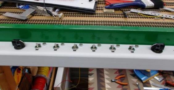
|
Down Main Storage Loops - Route Controls The two black rotary
switches select the routes (currently set for loop 3 /centre loop 3) into a
total of nine storage
loops. There is an identical set controls for the Up Main storage loops,
thence a similar of non-illuminated pair for the two Up and Down Branch
storage loops. |
Selection of Loops
Entry into each set of loops is switched by two
rotary switches controlling the turnouts at either end of each set of loops
(i.e. Entry into and Exit out of the loops).
Along the length of the two sets of five Up and
Down storage loops there is a maximum of six isolating sections with a five
-way rotary switches (at the entry and exit) route-selecting the each of five
sets of loops. The Down line is loop nos.1 to 5 (plus 1a, 1b, 5a & 5b) and
the Up line loop nos. 6 to 10 (plus 6a, 6b, 10a & 10b) tracks.
There are turnouts /crossovers mid-way down each of
the storage loop sections where (say) Down loops nos.1 to 5 all converge onto
an extension of storage road 3. However, these turnouts /crossovers also give
entry into four additional loops 1a /1b (from loops 1) and 5a /5b (from loop
5). These turnouts /crossovers operate automatically relative to the position
of the two sets of rotary switches.
On the Down Line whilst one switch (left) selects
tracks 1 to 5, the position of the other (right) can select either 1a, 1b, 5a
or 5b (else out via centre track no.3) with the intermediate pointwork
operating automatically to achieve this. However, if (say) track 2 is selected
(with no route into 1a (etc.) then the pointwork will automatically default to
departure via the centre track no.3.
The Up Line as a similar arrangement save to say
the centre track no.8 and additional loops are approached first. Rotary
switches are used in a similar way to control the Branch line storage loops (11
& 12) and fiddle yard tracks (13 to 16).
Finally, some of the Up and Down storage
loop’s five -way rotary switches have a sixth position which activate the
trailing crossovers at each end enabling reversal of pull-push /multiple unit
trains. Storage loops 10a or 10b being intended for the reversal of the London
Bridge to Ewhurst Green 8-car electric peak-hour terminating service.
The white operating panel is simple and robust,
being made from 50mm square section UPVC electrical trunking; the front removes
for maintenance access.
|
Down Main Storage Loops Section Switches Between the rotary
switches the six On /Off switches energise individual track sections; their
offset LEDs indicate which track sections are in use for any given route (not
all routes use all six isolating switches). There is an identical set controls for the Up Main storage loops,
thence a similar of non-illuminated pair for the two Up and Down Branch
storage loops. |
Isolating Sections
Each storage loop is split into isolating sections;
these sections differ in length, so some loops have six isolating sections (for
short trains); others just two (for longer trains). Rather than have large
banks of switches there is just one row of isolating switches which relates to
the storage loop selected by the rotary switches. LED lights illuminate in
order to identify which isolating switches apply to the selected storage loop.
For example, all six LEDs will illuminate for the
six (short-length) isolating-sections in storage loop no.1 and additional loop
1a /1b combined. However, just two LEDs will illuminate for the switches which
control the two (long-length) isolating-sections in (say) storage loop no.2.
Although sections 1, 2 & 6 are always needed they too are illuminated for
visual consistency.
Not only does this arrangement provide for simple
route-setting operation (reducing the margin of error) it both reduces the size
of control panel required along with the number of switches needed from 28 to 8
for (say) the Down fiddle yard tracks when compared to traditional switching
arrangements!
Two of the Up and Down storage roads (outer pairs 1
& 5 /6 & 10) can each access two additional storage roads (Down 1a
& 1b - 5a & 5b /Up 6a & 6b - 10a & 10b) so both an IN and OUT
rotary switch is needed; the relative position of each automatically sets
crossovers midway along the main line fiddle yard loops. There is a trailing
crossover at each end of the mainline storage loops and two of the four black
rotary switches have a 6th position to control these.
Operation of Isolating Loops
Along the length of the storage loops there is a
maximum of six isolating sections with a five -way rotary switches (at the
entry and exit) route-selecting the five loops. The six on-off isolating
switches (to be technically correct switching-off) activate the sections in the
selected storage lops with all other loops automatically switched-out.
|
Storage Loop |
Number |
Additional |
Equiv. Coach Lengths |
|
|
Down Line |
|
|
|
1 |
3 |
(1a & 1b) |
5 |
|
1a |
(from 1) |
3 |
5 |
|
1b |
(from 1) |
3 |
5 |
|
2 |
2 |
None |
9 |
|
3 |
2 |
None |
8 |
|
4 |
3 |
None |
8 |
|
5 |
3 |
(5a & 5b) |
4 |
|
5a |
(from 5) |
2 |
4 |
|
5b |
(from 5) |
2 |
4 |
|
|
Up Line |
|
|
|
6 |
3 |
(6a & 6b) |
6 |
|
6a |
(from 6) |
2 |
6 |
|
6b |
(from 6) |
2 |
6 |
|
7 |
2 |
None |
9 |
|
8 |
2 |
None |
8 |
|
9 |
3 |
None |
8 |
|
10 |
4 |
(10a & 10b) |
4 |
|
10a |
(from 10) |
2 |
4 |
|
10b |
(from 10) |
2 |
4 |
|
|
Down Branch |
|
|
|
11 |
5 |
None |
5 |
|
|
Up Branch |
|
|
|
12 |
5 |
None |
5 |
|
|
|
|
|
Isolation of the storage loop /fiddle yard tracks
is undertaken through the route setting in order to do away with the vast
arrays of switches so often seen on layouts. Instead, each of the isolating
switches only refer to the tracks upon which each route is set (this is
covered later). The wiring is simple and straightforward if not
time-consuming (particularly as fishplates are not relied upon for
conductivity).
There is no common return in these loops; for by
using one set of the turnout motor’s switch-contacts only the return rail
of the selected track is connected to the layout’s common return. This
means power can provided through each isolating section on /off switch across
five roads; but a train can only move on the storage loop selected and
connected to the layout’s common return. Simple but effective.
Ultimately some storage loops may be fully
automated using infrared detectors.
Relay Operation
Visiting sound locomotives and multiple units
identified some voltage drops in the storage loops, in part due to the length
of some cable runs. Whilst not a huge issue the decision was made to eradicate
these commencing with the layout’s London end storage loops.
A termination board for thirty type 600 relays
(mounted in a large GPO can to one side) was prepared. This is not easy for
access to both front and rear of the relays is required for future maintenance.
There is one 24-volt relay for each isolating
section with the relay wired in parallel with the turnout relay. Up to five
relays are operated from the existing (but reused) on-off switch on the panel.
However, only of these five relays can be energised (with the selection of the
designed loop).
As a consequence, all the voltage drops were
eliminated. However, I do need to prepare a diagram to visually express all
this as the reality is quite straightforward!
Power Supplies
On my previous layout (Apothecary Street) old
H&M /Triang /GPO 12v power units were utilised along with 50v GPO power
supply units (PSUs); the latter being purpose-built by the GPO and metal
encased. As a temporary measure these old 12v power units had been reused on
Ewhurst Green. However, going forward six-number modern PSUs with a higher
smoothed output (10 amp each) were always envisaged; these are mounted in
protected enclosures because of the exposed mains inputs.
Ewhurst Green uses five voltages with 12-14v DC
being the most common. However, the signals run at 9.5v DC, the turntable
operates at 16v AC, the storage loops /fiddle yard type 600 relays at 24v DC
and the type 3000 GPO relays in the station’s conditional locking use 50v
DC. The 50v supply comes from the purpose-made ex-GPO metal-cased power supply
units (as previously mentioned).
Excluding some of the controllers which have an
internal power supply unit (PSU), the six number DIN-rail mounted PSUs are
employed in pairs; each with a smoothed ten-amp DC output. Four of these are
linked to provide +12v /0v /-12v for the ninety-nine relay-operated Tortoise
turnout motors.
Each Tortoise motor is operated through a 24v
relay, so power is taken from across the +12v /-12v transformer taps to give
24v for the type 600 relays used in the turnout-motor controls. Although the
type 600 relays will operate on 12v, their operation is much improved with 24v.

|
One of the 12v /24v twin 10A locking power supply
cabinets. |
Each PSU draws 2.6 amps from the mains, these
transformers are fed through a surge protected supply taken off one of the
isolating ring mains in the track room. In other words, these ring mains can be
powered down when leaving the track room.
Mercury Displacement Relays
All these transformers are plugged into the
track-room’s lower ring main in pairs; the total current draw of all six
main 10-amp transformers alone being 15.6-amp (then there are all
the controllers and secondary transformers) so these are supplied through three
separate 13-amp plugs.
To avoid the tedium of switching off each plug
individually (including forgetting to do so), a single master switch for the
layout has been installed which powers up two Michigan-built MDI Mercury
Displacement Relays in the far side of the track-room. These Mercury
Displacement Relays now energise two of the 13-amp supplies to four of the main
power supply units (balanced with other transformers and controller loads).

|
Mercury Displacement Relays being bench-prepared
in a locking cabinet. |
Photographed
on the bench (but now mounted, wired and commissioned into use), the power feed
to the Mercury Displacement Relays will enter (in trunking) the underside of
the cabinet to the Blue /Earth Live terminals up on the left. The 2.5-amp
switched circuits will enter in the top from a control cabined immediately
above; brown for LH relay blue for RH relay. As these Mercury Displacement
Relays operate at 120v they are wired in series you can hear the slight deep
hum when energised!
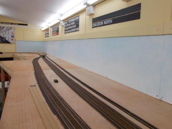
I wonder how many other model railways use these?
Chapter Sixteen
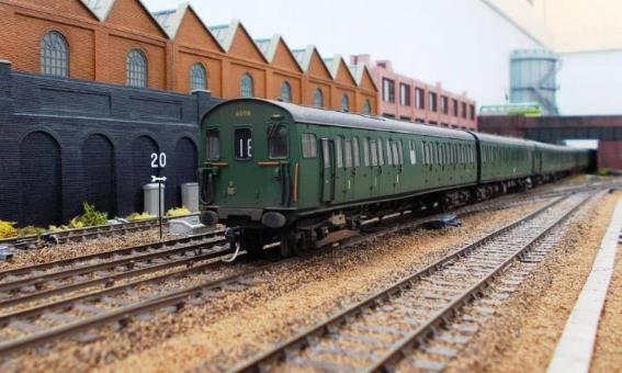
|
The test track was pulled away from the back wall
to enable the painted sky-boards to be fixed in place; their top edge
slipping under the beading. Country end S&C. Six sidings can be seen starting to curve away
to the right; beyond is the junction where the non-electrified double-track
branch will curve away to the right from the electrified main line. |
Painted Sky
After much consideration, a simple painted sky back
scene was opted for; this being very effective on a friend’s P4 layouts
of Oxted and Redhill. It also enables the future use of trompe-l'oeil
behind the trees in order to provide the effect of depth. Furthermore,
Ian’s adept and creative wife Wendy had offered to paint it her work was
excellent!
Each scenic board was numbered and painted
matt-white ready for Wendy to undertake her magic with sponges and various
acrylic paints; the sky effect being carried across each board joint (completed
March 2017).
Unfortunately, the room’s daylight simulation
lighting means the photographs simply do not do the final sky-effect justice.
However, they look excellent in-person and I’m extremely grateful for
Wendy’s creative time and work.
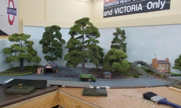
|
London direction - D6580 is sitting on the Down
Main. Left to right - Up Loop no.1, Up Passenger Loop, Up Main, Down Main (with the realigned temporary test circuit
alongside) |
Backscene & Access to Lighting
Along the length of the scenic side of the layout
is a continuous support-bead originally intended to provide a firm rest if any
of the fluorescent strip light’s high-frequency electronic ballasts
needed to be replaced. Essentially leaning over a scenic layout could present
logistical-reach issues; the support-bead (a beam with a lip) could enable a
flat board to be placed and supported above the layout reducing any potential
damage to the layout.
However, the use of LED replacement tubes left the
electronic ballasts redundant reducing the potential need for maintenance
access (the LED tubes are easily reached). It does highlight the benefit of
using LED replacement tubes instead of integral LED light fitting which require
complete replacement when they fail a small stock of LED replacement tubes is
kept to one side.
High-frequency fluorescent lighting was originally
employed because they are strobe-free (for example, the strobing effect from
fluorescent lighting can be dangerous around moving machinery). They also had
improved starting, greater efficiency and longer-life. But in just a couple of
years LED lighting had superseded all of this with the electronic ballasts
wired out-of-circuit and the fittings re-wired to accept LED tubes.
The 16” height of this support-beading was
determined by using the 8” long 12mm plywood off-cuts from the
32”-wide baseboards. These 16” by 8” long off-cuts were used
to form the back scene; the top-edge of which is held in place by the
support-beading.
Since these photographs were taken the daylight
fluorescent tubes have been replaced with daylight LED tubes. Besides the
savings in electricity, maintenance is future-proofed; tubes can be easily
placed by reaching over the railway. However, had an electronic ballast
required changing it could have been tricky with scenery in place down below.
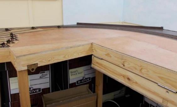
|
In typical 'before and after' style first
photograph is the timber former in place alongside the down headshunt. The
visiting BR Standard no.75008 is hauling a train on the Up Line with the
Reversible on the right-hand side. |
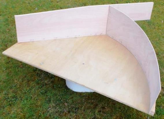
|
Passing under Somersbury Lane bridge
alongside the completed retaining wall, the six-car formation approaching
Ewhurst Green station on an Up service is led by 2 HAP no.6008. Expertly
weathered by TMC, this original-condition Phase 1 /Batch 1 unit was a relatively straight-forward conversion
using parts from a 2 EPB. The conductor rails are installed although minor
adjustments to the S&C are occasionally taking place. Only then will more
scenery be added between the running lines and carriage sidings curving away
in the foreground. |
Decor
At the same time as this scenic-backboard work was
undertaken, the opportunity was taken to add some room decor in the form of
split-flaps from former Solari indicator boards (obtained during my days on BR’s Southern Region). These
provide a selection of destinations and types of indications displayed
including some no longer seen.
Towards each end of the scenic section the scenic
track curves around towards the fiddle yard. The intention here is to place
suitably positioned bridges at the start of these curves with the scenery
designed to give a visual impression of the track continuing straight on; the
curves being hidden from view.
Chapter Seventeen
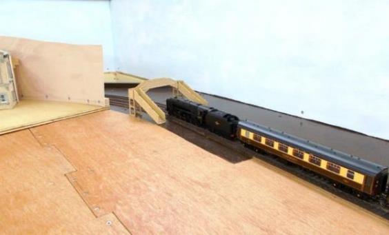
|
Trompe l'oeil ( Deceive
the Eye'). At the London-end of Ewhurst Green, trains will
pass under the footbridge before disappearing from view. This is
achieved by a curved board in front of the track; itself obscured by trees. Six trees have
been positioned on this curved board with work progressing (left to right) on
the groundworks (foliage) which will soften up the skyline at ground level. A
seventh tree is beyond the railway line; part of an eighth is just visible in
a front garden. In reality the
sky is far ‘less’ blue that it appears here in these photographs. |
17. Trompe l’oeil
‘Deceive
the Eye'
Trompe l'oeil essentially
translates to ‘deceive the eye' and is a technique of using realistic
imagery to create an optical illusion of depth. In this case to enable the
track to disappear from view, whilst hiding the curves round to the fiddle
yard.
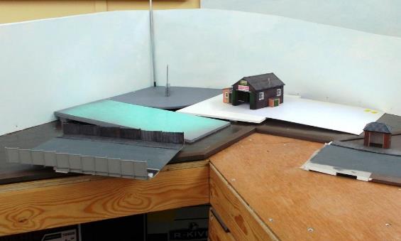
|
London-end curve (with the scenic access flap
folded). The ends of the non-scenic turntable are visible on the left. |
Work during Easter 2018 included installing two
removable curved scenic boards especially constructed for either ends of the
scenic section. Once these were painted (sky-background) the scenery including
trees (both modelled and painted) was added. The intended effect (trompe
l’oeil) is to allow trains to disappear from view without resorting to
(say) artificial looking tunnels.
The London-end curved board hosts a village garage
(off Horsham Lane) while the curved board at the Country-end has the Woolpack
public house and Somersbury Lane.
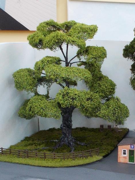
|
The London-end removable scenic curved board. Awaiting
sky-painting ; the track will pass around behind the curved board (right).
Trees will increase the perception of depth behind the model trees in positioned
front. Removable, the board lifts out to provide access. A notch will be cut
in the front edge for the sloping highway that crosses onto the board at a
skew. |
At the London-end of the layout there will be a
concrete footbridge and Horsham Lane level crossing (the Country-end will
comprise of Somersbury Lane road-overbridge crossing
both main and branch lines).
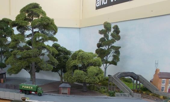
|
Once the curved board is sky-painted this train
will be disappearing under the footbridge thence out of sight behind the
board, itself obscured by many trees yet to be planted. The locomotive is sitting across the (to be)
level crossing with the concrete footbridge positioned on its London side. |
The highway (Horsham Lane) climbs slowly (1 in 20)
away from the level Crossing across the board with its notched-joint (to
mitigate the skew). However, a mechanism was needed to cover this joint. So, in
May /June 2022 a short lift-out section of highway was prepared with pavement
/shabby wooden fencing on one side and grass verge /concrete panel fencing
(against railway land - Goods Yard) on the other.
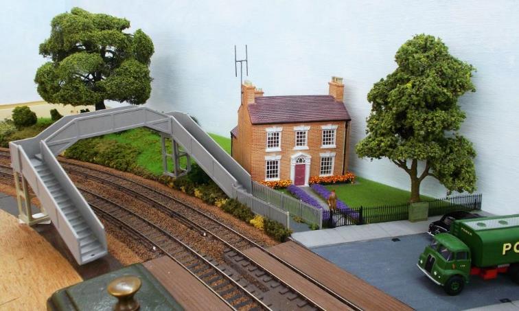
|
Lift-out highway section. With the base of the curved board notched, the
removable section of road illustrates how the gap is covered up between the
grey road (right) and blue unpainted road (left). Behind is the village garage and its proposed
yard area. |
As Horsham Lane continues to climb across the
removable lift-our section, there is a flat section ready for the village
garage. At the rear corner of the curved board (in the photograph above)
the end of a long silver /black screwdriver sits in one of hidden screws that
holds the brown-painted vertically-curved foamboard down. This was needed due
to an Oak tree’s exposed roots stretching right out (the tree centre
being marked by a set square on edge); these roots needing to be glued to the
foamboard. However, this Oak tree section with its foamboard can still need to
be removed if absolutely necessary.

|
Hiding the corner of the curved board Awaiting final fixing down this superb Oak with
its exposed roots sits in the corner of the curved board. Outside of the tree’s canopy (dripping
water could adversely impact on flight paths), a beekeeper attends to some
hives. |
A village garage sits adjacent to the Horsham Lane
(this being a Bachman Hampton model cat. no.44-076). A tree will be positioned
to the rear of the garage with a large tree anticipated to its right (and two
smaller ones behind) again to hide the corner and assist in the illusion of the
train simply disappearing from view.
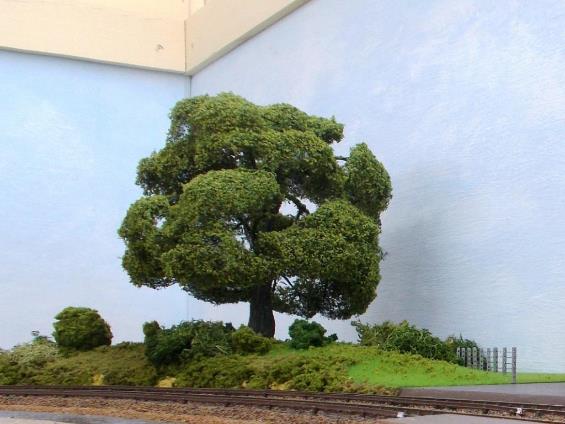
|
Obscuring the curved board’s vertical edge. Surrounded by others, a suitable tree obscures
the vertical sky-edge of the removable scenic curved board. The overall effect will be for the train to
disappear out of view. |
In the photograph above, the tree hiding the curved
board’s vertical sky-edge sits on a triangular fill-in brown-painted
board (awaiting foliage) along with an omnibus shelter. Final fitting including
ground-level foliage, and a hedgerow is still to be undertaken.
Chapter Eighteen
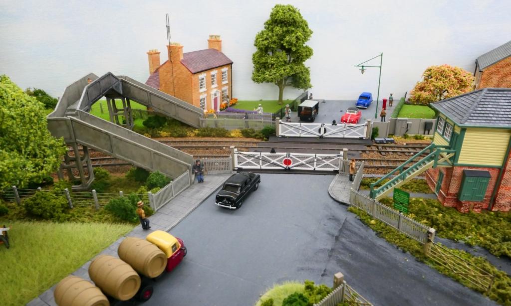
|
When Ewhurst Green station was enlarged a footbridge
became necessary alongside the altered Horsham Lane level crossing; access to
which required encroachment into the front garden of Lavender House . Here
the level crossing is still under construction (as is the Up side scenery). |
May 2018 saw the first of the scenery added to the layout and is has been gradually progressed along the rear of the scenic board as greater access is required to the running lines until they have been fully tested across all routes.
Although essentially a rural area it was determined
that with the coming of the railway some local industry (probably
agricultural-based) was inevitable. It was decided that this part of the
scenery would be started first followed by the adjacent removeable curved board
with its public house (Country-end).
Since then, work has also started on the scenery
adjacent to the level crossing and this will extend onto the other removable
curved board (London-end).
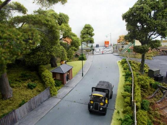
|
Even prior to commencement of the layout’s
construction, a significant number of hand-made trees had been purchased from
Ceynix in readiness; to a scale size these being
absolutely excellent. On the right in the railway fence thence part of the
rear garden of a house. (This tree was subsequently relocated). |
Trees
Trees are an
important part of Britain’s landscape; some Yew trees are older than the
Pyramids. So many trees are modelled undersized in 4mm; a large mature tree
will be taller than a railway coach is long. As already seen in the section
about Trompe
l'oeil, at the ends of
the layout’s scenic section (the London-end in particular) trees on the
curved boards will help to hide the disappearing tracks; many of these having
been purchased from Ceynix. Some are over a scale 100’ in height the
average being 65’ with many UK trees doubling this!
May 2018 saw the first of the scenery added to the
layout and is has been gradually progressed along the rear of the scenic board
as greater access is required to the running lines until they have been fully
tested across all routes.
Chapter Nineteen

|
Horsham Lane level crossing. It was decided at any early stage to have fixed
level crossing gates as operating gates would have been an ongoing
maintenance whilst seeing little use. Furthermore traffic queuing at a set of
open gates might appear rather odd. |
19. Horsham Lane (London End)
Horsham Lane, its level crossing and footbridge is located at the London End of Ewhurst Green station where the railway disappears from view behind scenery.
Horsham Lane Level Crossing
The Horsham Lane
level crossing is a fully-gated skew crossing with ex.LBSCR
Mackenzie &
Holland gates. However, these level crossing gates are non-working (i.e. fixed).
Essentially the fitment of less-robust working gates was likely to become an
underused gimmick whilst being an ongoing nuisance to maintain. Each pair of
gates and their level crossing timbers can be easily removed for maintenance or
access.
Besides being
visually different, the shew crossing also assists in accommodating the signal
box steps whilst keeping the signal box reasonably close to the level crossing,
thus enabling the signalman to oversee its operation. It had long been decided
to use the Hornby Horsted Keynes signal box except its steps were at the wrong
end of the box when used on Ewhurst Green. However, both the skew and being
pushed-back behind a headshunt tend to negate this.
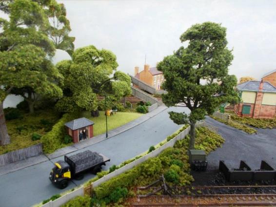
|
The approach to
Horsham Lane level crossing (with its Mackenzie & Holland gates) is now
looking very rural. The positioning
of trees was deliberate making it difficult to view the crossing, footbridge
and adjacent cottages from a single vantage point. |
Two houses had been
earmarked for the far side of the railway, to be placed either side of Horsham
Lane. Most houses in
the Surrey village of Ewhurst are set well-back from the highway and so both
these houses will have front gardens; in this case deep enough for a small tree
in each.

|
Horsham Lane
curves round gently to the level crossing on a slight falling gradient. To
the left of the footbridge behind the bus stop a tree hides the scenic
backboard with assists with trains in disappearing from view. On the right
part, of the ex. LBSCR Signal Box is visible; this being now demoted to a
Level Gate Crossing box. Below is
virtually the same photograph shewing how a single tree can significantly
alter the view meaning the viewer now has to physically move to be able to
see all. |

The concrete
footbridge sits on the London-side of the level crossing, this being a repaired
/repainted /updated Hornby-Dublo model that had previously spent over four
decades in one of my oddments boxes. If the level crossing ever had wicket
gates (Country-side) then these were abolished (being replaced by the
footbridge) when the station was remodelled to make room for the facing
crossover into the (then new) Up Passenger Loop.

|
Horsham
Lane’s new concrete footbridge encroaches into the front garden of
Lavender House . Hopefully many
will remember the BBC ‘H’ television ariels and daily door-step
milk deliveries by milkmen using electric milk floats. Street lamps used to
be located just behind the kerbstone. |
Lavender House
Bachmann’s
Georgian house (44-077) has a suitably appropriate double frontage and elegant
front door and surround. Horsham
Lane’s subsequent concrete footbridge encroaches into the front garden of
Lavender House with its BBC ‘H’ television ariel (for reception of
the 405 lines signal). Besides the milkman, the housemaid is busy cleaning the
windows.
Two more of these
houses are used on the layout albeit with only their rear aspects visible.
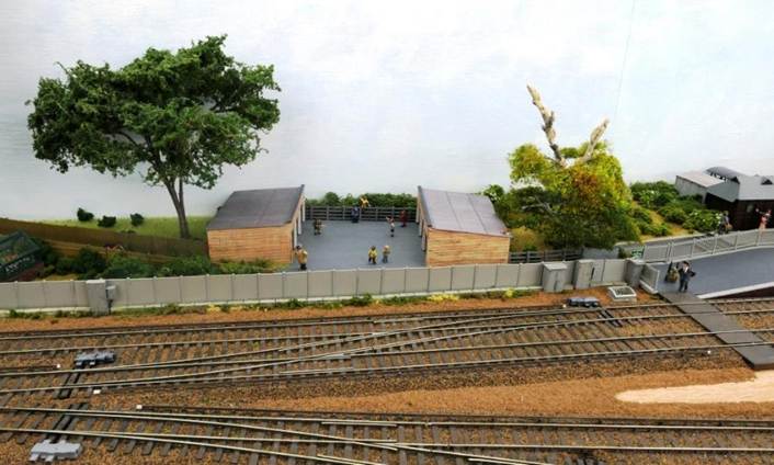
|
Separated from
the railway line by a concrete panel fence, Cherry Cottage sits opposite the
coal yard. Washing is being put out while a boy plays with his dog
(Bachmann A1936). Flowers fill the Hornby greenhouse (R8682). Both trees are Ceynix; one is a scale 95’ high. The house is Hornby (R8561) with Bachmann concrete coal bunker
behind (44-538). The half-buried and overgrown Anderson shelter is a Hornby
model (R8987) with a Unit Models Garden shed alongside. |
Cherry Cottage
With cherry blossom
on the tree in its front garden, Cherry Cottage sits opposite Lavender House.
Hornby’s Aswell House (R8561) was selected as Cherry Cottage for it has
both interesting front and rear aspects (particularly when viewed from one
corner-angle as seen here).
In its rear
garden is a concrete coal bunker, overgrown and part-buried wartime Anderson
shelter, garden shed and greenhouse. Washing is being hung out to dry while a
child and dog play.
Alongside Cherry
Cottage’s rear garden is a narrow private access road between garden
fences along to some lock-up garages used by local children as a play-area.
This private access road also provides pedestrian access (footpath) to the
station (via steps at its far end) and to a station café adjacent to the
station forecourt.
Small independent
manufacturers such as Unit Models also produced details such as Pidgeon lofts,
garden sheds and so forth. Hornby even made model Anderson shelters (these were
intended to be part-buried and earth-covered) with the houses adjacent to the
Horsham Lane level crossing being constructed on 5mm foamboard cutting a hole
for one of these part-buried shelters was straightforward.
Issued free to many householders in
areas expected to be bombed by the Luftwaffe, the first self-build 'Anderson'
shelter was erected in a garden in Islington, London on 25th
February 1939. Designing engineer William Patterson had been commissioned by
Sir John Anderson (in charge of Air Raid Precaution) and by the outbreak of the
war in September 1939 some 1.5 million shelters were distributed (with further
2.1 million thereafter). Constructed from corrugated steel by John Summers
& Sons (of Shotton, North Wales) each measured 6ft.6 in. long, 6 ft. high
and 4 ft. 6 in. wide and were made of 14-gauge galvanised steel sheet.
Immensely strong, each were intended to be sunk 3ft into the ground and covered
with soil although many subsequently suffered ground-water flooding.
A small selection of buildings was initially set
aside (such as a village garage) so choices can be made nearer the time. My
previous layout (city-based Apothecary Street) had a significant collection of
buildings so there were many to choose from with a large unused surplus being
sold on.

|
The lock-up
garages attract the local children; here playing Cowboys and Indians while an
unamused adult busybody watches on disapprovingly. |
Lock-up Garages
The two blocks of
three garages are Bachmann (44-083) and came equipped with up-and-over doors.
Although this type of door existed pre-war, they were relatively uncommon in
the fifties and early-sixties. A decision was made to fit Ewhurst Green’s
garage blocks with wooden doors, although these can be replaced with
up-and-over doors either in the open or closed position.
It is suggested the float over door may have been around since 1902, and
in 1921 the Overhead Door Corporation introduced an up and over door which
lifted upwards and folded parallel to the garage ceiling. However, it
wasn’t until 1936 when the first one-piece overhead type garage door was
invented.
Alongside the garages there is an alleyway up to the station (a
feature of many railway stations) passing under the lightening-struck tree with
its new growth; a cat on top of the right-hand garage block watches pedestrians
come-and-go.
Chapter Twenty
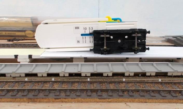
|
Ewhurst Green’s
Down Side station building. |
20. Ewhurst Green station
May 2018 saw the first of the scenery added to the layout and is has been gradually progressed along the rear of the scenic board as greater access is required to the running lines until they have been fully tested across all routes.
Station Buildings
Bachmann’s Thomas Myres Sheffield Park tile-hung station building
is simply superb and far too good to pass up! It comes in several parts:
Waiting Room (44-087) up side
Booking Office (44-088) down side
Station Canopy (44-089) down side
Waiting Room (44-090) down side
Store Room (44-091) down side
The
platform-mounted signal box was not required. The main station buildings were
to be positioned to the rear of the layout (down side) so the platform-side
could be seen. Furthermore, the up side was going to encompass the station
goods yard; a practical decision in terms of accessibility during shunting.
Produced in LBSCR
colours, a friend offered to repaint the buildings into Southern Region colours
for at the time I was recovering from eye-treatment. Whilst the station
footbridge had also been made, because of the canopies the decision was made to
equip the station with a subway instead.
Hornby had produced
its Rye-based Terminus Station Building (R8713) and (with accompanying Terminus
Station Offices (R8714) and whilst these are super models, they were not as
imposing as Bachmann’s model and would relate more to Ewhurst Green (East
Sussex). So, the purchased set are currently stored. Similarly, Hornby’s
High Brooms building (R9818) was also rather nice, albeit smaller in size and
really relating to the new road to Hastings.
A set of
Bachmann’s Shillingstone’s station
buildings had also been previously purchased although not for this layout.
Station Platforms
Much of Ewhurst
Green’s ten-coach platforms are on a long-transitioned curve probably
around twenty feet radius although at some state this ought to be confirmed by
measuring its versine. So, this curve meant constructing a bespoke platform to
suit the changing radius of the curve. The only consistent distance being the
96mm between nearest running edges of platform 4 and platform 3’s tracks.
The Department of
Transport’s Railway Construction and Operation Requirements for
Structural and Electrical Clearances (commonly referred to as the ‘Blue Book’) states the
platform face should be 730mm from nearest running edge equating to 9.58mm at
4mm=1 . Having established (including through testing during running sessions)
that 12mm from nearest ‘OO’ running edge to edge of copers was a
suitable compromise (including allowances for throw & inaccuracies
/movement of model rolling stock) plus the 5mm depth of Peco platform edging, a
means of scribing the platform top at 17mm from the nearest running edge ready
for trimming was required.
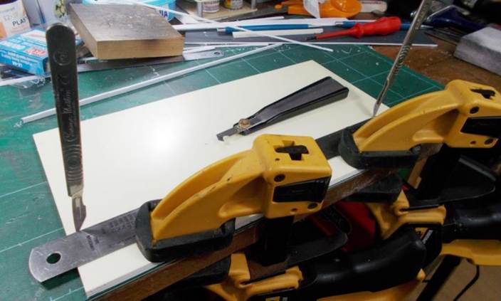
|
Underside of the platform scribing wagon |
The solution was
relatively straightforward and involved mounting a foamboard cutter on an old
Hornby-Dublo wagon underframe (the wheelsets being opened out to remove lateral
throw and with no end-float in the axles to aid precision).
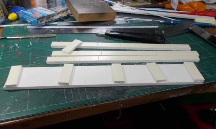
|
The 5mm foamboard is clamped ready for cutting
into strips with the two scalpels being used to line up the straight edge.
Resting behind is the Tamiya plastic scribing tool used to gradually cut
through the board. |
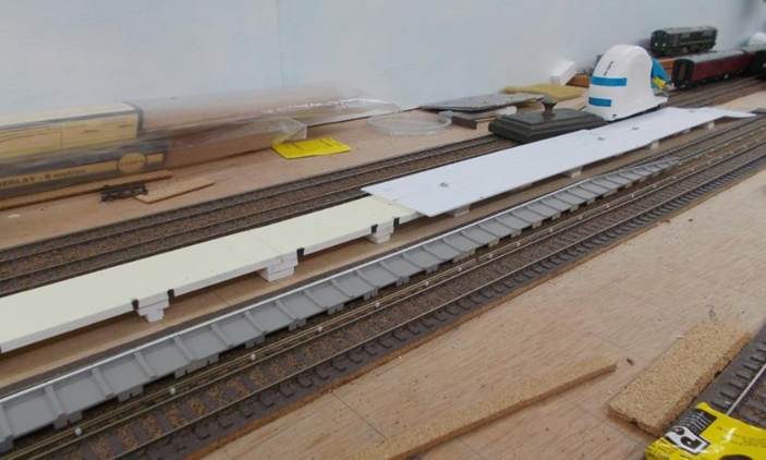
|
Resting upside-down on the bench, the platform
construction uses three layers of 5mm foamboard thence another 3mm to bring
it up to the correct height for its plasticard surface. |
The platform
structure was built up using 5mm foamboard, thence 3mm board /plasticard for
final packing to get the final height this being first glued to the underside
of the platform surface in order to smoothen out the joins. The track is laid
on 3mm cork with the Peco platform edges mounted on the baseboard (it leaves
the platform surfaces about 1mm too high).
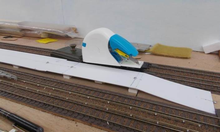
|
The foamboard platform construction with platform
surfaces screwed in place centre and right. Resting in the six-foot is a
length of painted Harp & Slab platform face. |
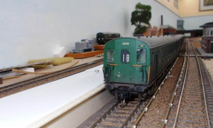
|
To the left the platform top is awaiting
scribing; centre and right it has been trimmed and fettled. |
With deliberately
over-wide sections of the platform surface firmly screwed in place, the
platform scribing wagon could then be run along both tracks to scribe cutting
lines ready for trimming on the work bench.
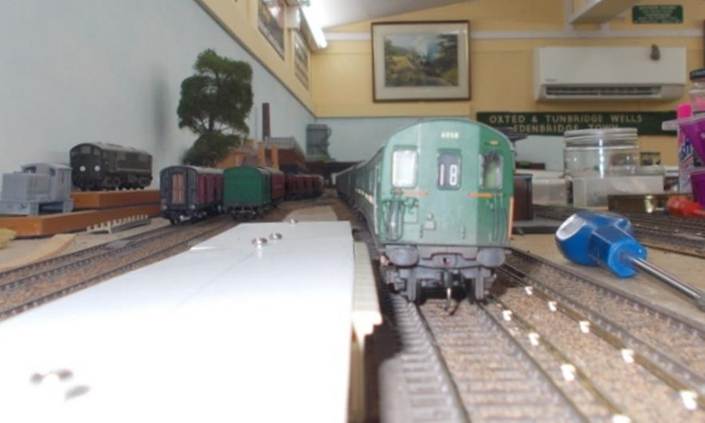
|
A section of Peco platform edging is temporarily
slipped into place to check the platform clearances are correct. |
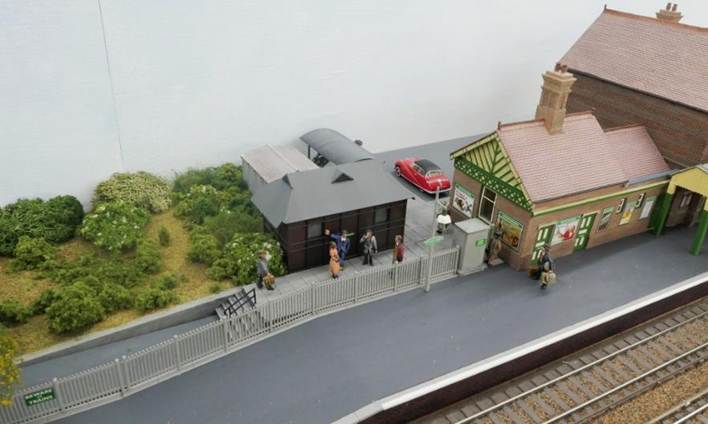
|
Edge of the platform coping stones sitting at
12mm (rather than 9.58mm) from the nearest running edge. The platform surface
has yet to be primed and painted. |
Whilst being
fettled on the workbench, the platform surface’s shape was duplicated
with 30-thou plasticard in order to provide a former for construction of the
platform canopies.
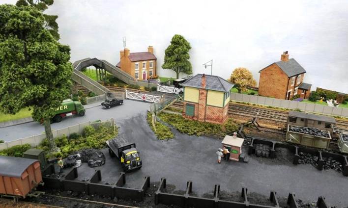
|
Local Teddyboys loiter outside
the small station café while a passenger has her ticket checked as she
leaves through the side gate (the porter behind is struggling to keep up as
he carries her three heavy cases). A short flight of steps with centre handrail lead
down to the alleyway. |
Station Café
A Wills
Taximan’s Rest (based on London’s Cabman’s Shelters) was
employed for the station café ; this being reasonably appropriate for
the period and location.
The Cabmen's Shelter Fund was established in 1875
London to run shelters for the drivers of hansom cabs and later hackney
carriages. These shelters were small green huts, which were not allowed to be
larger than a horse and cart, as they stood on the public highway. Between 1875
and 1914, sixty-one of these buildings were built around London (the first
being on Acacia Road in St John's Wood). With a small kitchen at one end, the
majority were staffed by an attendant who sold food and drink to the cabbies. The
thirteen survivors are now Grade 11 listed and having used the one in Grosvenor
Gardens many times (along with the long-gone Taximan’s café under
St Pancras station) the building (originally procured for my Apothecary Street
layout) seemed to form a nice basis for a station café .
Like many stations,
the adjacent side gate with its concrete ticket collector’s shelter was
quite typical being opened for selected trains; particularly the busiest
peak-hour arrivals.
Behind the
café is a cycle shelter and a pre-cast concrete railway storeroom.
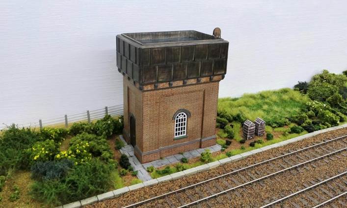
|
With modernisation of the signalling,
Hornby’s Horsted Keynes Signalbox was delegated to the role of a
crossing box. Buffer stops are LBSCR-type from Lanarkshire Model Supplies. An angry
customer remonstrates with the Coal Merchant as (from the top of the signal
box steps) a bemused Signalman looks down upon the commotion playing out down
below. |
Station Detailing
Most of the station
staff and passengers are either from the excellent Aiden Campbell 4mm range
(sadly no longer available) else Dart Castings with a few more from other
small-scale manufacturers. However, these are covered in the section on
Passenger Traffic .
There are also
little detailing gems from the distant past such as a set of Mike’s
Models (of Caswell Bay) Laundry Baskets (cat. No.313) albeit now with a
snoozing porter sitting on them awaiting a colleague to help him load them.
At the buffer-stop
end of Bay Platform 4 is a Southern pre-cast concrete Lamp Hut from NMB models.
This company also produced a concrete ticket collectors hut (positioned at the
side gate opposite the station café) and a precast chemical toilet (for
use in the yard). One of their accommodation building kits will also used.
Signal Boxes
Further to the
Sheffield Park station buildings Bachmann also produced several Southern signal
boxes which were obtained for possible future use:
Art Deco Type 13 signal box (44-064) similar to
Horsham, Templecombe, Bognor Regis (etc).
Kent Coast Type 17 signal box (44-064Z) similar to
Rochester (complete with modern aircon unit).
LSWR Type 4 signal box (44-087Z) stone-built.
LSWR Type 4 signal box (44-061Z) brick-built
similar to Bude.
LSWR Type 3 signal box stone-built.
Hornby also
produced the following signal boxes which were also obtained for possible
future use; experience having shewn if you don’t purchase these when they
are released it can prove very difficult to obtain them later.
Horsted Keynes signal box (R8955).
Art Deco ‘Deal’ Type 13 signal box
(R9729).
|
Rear of Horsham’s Art Deco (former) signal
box. |
Models of
Petersfield, Wateringbury and Robertsbridge signal
boxes have also been produced by manufacturers although Robertsbridge was sadly
modelled with is post-1974 extension. In addition, the Hornby R6863 model bore
similarities to Saxby & Farmer boxes.
Of those purchased,
Bachmann’s superb Art Deco ‘Templecombe’ Type
‘13’ signal box (as previously used on Apothecary Street) would be
used at the country-end of the station (just off island platform 1 & 2) and
the Horsted Keynes signal box will be demoted to a gate box controlling the
London-end Horsham Lane level crossing; the latter was a design specifically
used south of East Grinstead.
Unfortunately, the
delightfully diminutive Art Deco ‘Deal’ Type 13 signal box
isn’t particularly impressive when viewed from the rear and two Art Deco
signal boxes would be improbable.
Most of those
signal boxes not required have since been sold on to modellers who are
(hopefully) making good use of them!
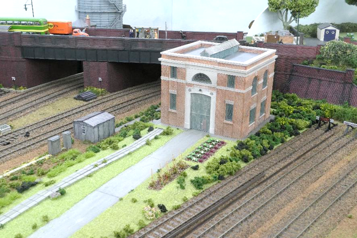
|
Ewhurst Green’s Cathedral sub-station still
retained a couple of well-tended vegetable plots on its approach. |
Sub-station
Bachmann produced one of the early manned 1932 Cathedral Electrical
Substations (44-069) and the history of electrification scheme to Ewhurst Green
was deliberately written as being early in order to justify one of these superb
models. The building is much reduced in size from the original. However,
situated towards the country-end of the station it will deliberately obscure
direct line of (viewing) sight under the road overbridges. To their credit
Bachmann also produced a later lineside sub-station (44-043) albeit again much
reduced in size from the original. The use of one of these was considered but
the Cathedral-type (model again shortened when compared to the original) would
fit in more comfortably on the layout and its electrification period.
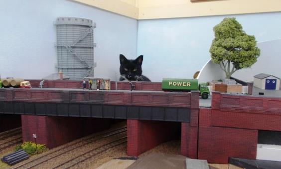
|
LBSCR water tank. Adjacent to the tank, a member of railway staff
has set up some bee-hives - something no longer seen lineside. |
Miscellaneous Railway Buildings
Over the years a
number of miscellaneous railway buildings have been acquired for the model
railway. Decades ago, Roxey Models made the SR concrete Permanent Way hut and
tool shed pairing (cat. no.484), Bachmann the SR concrete ballast bins (44-500Z
of which several are located on the layout), NMB models a concrete lamp room,
Ratio the delightful concrete Fogman’s Hut - one of these may make an
appearance although in real terms it probably wasn’t really justifiable.
Kernow produced the
SR water cranes (44-120Z) braziers (44-550) being available if needed. However,
Mike’s Models produced both excellent LBSCR platform-mounted fluted water
crane (cat. no.10) and SECR water crane kits and several of these were procured.
Bachmann produced a
model of an ex. LBSCR water tank (essentially that located at Sheffield Park
although not advertised as such). Fortunately Arcadia
Models of Shaw were able
to supply one - ordered at 3pm Friday, it arrived at 10.30am the next-day.
Hornby had (as a
special) produced a Southern country station building (R9642) and a couple of
these were obtained lest they could prove useful. However, the derivation of
this building remains unclear, these became surplus to requirements and were
sold on.
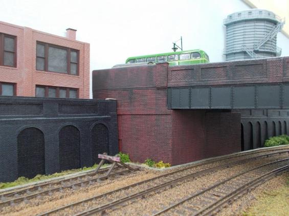
|
Carriage Cleaner’s Walkway The installed walkway with mid-point steps. Note
the adjacent boarded conductor rail these days relocated to the side furthest
from the walkway. |
Carriage Cleaner’s Walkway
Located between the
eight-car electric siding and non-electrified carriage siding is a full-length
carriage cleaner’s walkway. The walkway was installed in two four-car
lengths (uncommon but not unheard of) in order to provide a visual indication as
to the location of the electric siding’s uncoupler lest coaching stock is
positioned over the non-electrified siding’s uncoupler. It also provides
a degree of mitigation lest the walkway is damaged and needs replacing.
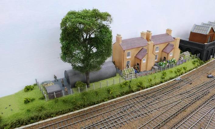
|
Installing the Walkway The walkway is an interference fit in the 3mm
cork underlay between the sidings with pre-cut strips of ballasted cork
inserted between each pier. |
Ratio part no.544
was used for the walkway although with scale track, its feet do (like the
original) need to be buried to provide the correct height. This need was
addressed very early on in the design of Ewhurst Green by providing a narrow
slot in the 3mm cork underlay between the two sidings.
The walkway was
fabricated in single sections and (with strips of 3mm ballasted cork) inserted
one length at a time; both being an interference fit so could be prised out for
future repair or replacement.

|
Walkway at Horsham’s Malthouse siding with protection boarded
conductor adjacent (May 2008). Note the modern anti-slip surface, white edging and steel handrails
fitted to the rear. |
Although time
consuming, this yielded the desired effect indeed the line of the walkway
looked too good when compared to a number of real-life slightly misaligned
examples.
Chapter Twenty-one

|
With a large tree still to be positioned in the field, the Woolpack
Public House sits within an otherwise seemingly rural area on this side of
the railway line. However, behind the Cathedral sub-station there is a modest
agricultural factory on the far side of the railway bridge. The thick dark patches of foliage are Lars op t Hof Scenery (in front of the fence and on the embankment side). Much of this scenery was supplied by Model
Scenery Supplies of Cromer. |
21. Somersbury Lane (Country End)
May 2018 saw the first of the scenery added to the layout and is has been gradually progressed along the rear of the scenic board as greater access is required to the running lines until they have been fully tested across all routes.
|
With the distressed retaining wall in place (save
the corner-pillar), the footway in front is now being fabricated on the
falling grade. A large tree has been selected to sit behind the pub with
another alongside. Bereft of detail & currently looking quite
stark, opposite Somersbury Lane, an embankment was
already envisaged down into a field. |
Woolpack Public House
Bachmann produced
an excellent tile-hung village pub (42-124) named Woolpack . Not
untypical for a Surrey /Sussex /Kent public house, this is an impressively
large model and sits well at the country end of the layout, with the highway
dropping down in front of it. Indeed, with its till-hung frontage and
white-washed walls this model shares some visually basic similarities with the Parrot Inn (Forest Green) and
the White Hart (Cranleigh).
Pubs in Ewhurst included the now closed Crown Inn (cl.1960), hopefully the Bull’s Head will continue as does the nearby Scarlett
Arms at Walliswood and the King’s Head at Ellens Green. However, the Windmill Inn (Pitch Hill) burnt down in
July 2021 and its future remains uncertain.
There is a Woolpack Inn at Elstead, Surrey so Bachmann’s pub name could remain
particularly given the local outcry when pubs seek to change their name.
Indeed, some pubs have chosen to revert to their original name following a
community’s refusal to acknowledge, let alone use the new name!
Providing a visual
contrast to the industrial buildings on the south-east side of the railway, the
Woolpack public house is located on the more-rural north-west side of
the overbridge having survived a regrading of Somersbury
Lane’s approach to the railway bridge when it was rebuilt (widened) to
accommodate the Cranleigh branch (the lane sloping up from a river bridge over
Cobbler’s Brook).
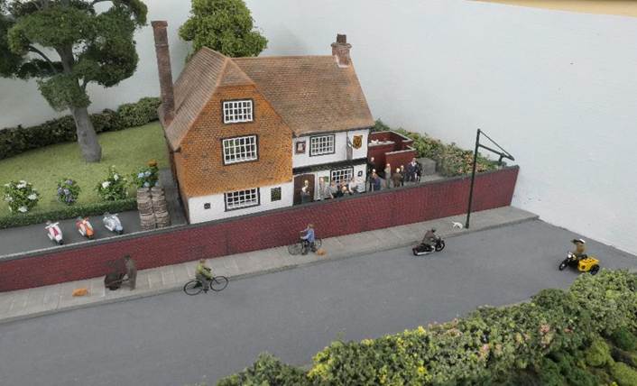
|
Just before opening time and customers wait . With cats looking down at customers (and their
dogs) from atop of its wall, two gentlemen (just visible) make good use of
the gent’s toilet. With one of his dogs snuffling on ahead, an
elderly man slowly pushes his cart up the hill while his other dog
investigates some interesting smells at the base of the streetlamp. Cycles
and motorcycles abound! |
Scenix produced an
out-door gent’s toilet complete with urinals (EM6113) and this formed an
excellent period extension for the pub’s main building; completed with a
couple of customers ..
From its signage
the Woolpack is a Whitbread pub (typical of the time) with both
‘AA’ and ‘Les Routiers’ accreditation. Within a couple
of years much of its garden would be covered in tarmac as the rise in motor car
usage increased.
Space could have
permitted a cottage or two opposite the Woolpack , but again, less is
more in this rural area. So, a field was provided at the foot of the rising
embankment with the roadway atop separated by an overgrown hedgerow. There are
a couple of galvanised cattle water troughs for the ponies in the field. However,
on the pub side of Somersbury Lane a small domestic
substation has crept in between the pub and the railway bridge (with a roadside
GPO telephone cabinet alongside).
The non-functioning
period streetlamps are very old hand-made models of unknown origin. Admittedly
not typical of Ewhurst, the streetlamps are mounted at the back of the
kerbstones modern practice now normally places streetlamps at the rear of the
footway and at least 450mm from the kerb line.
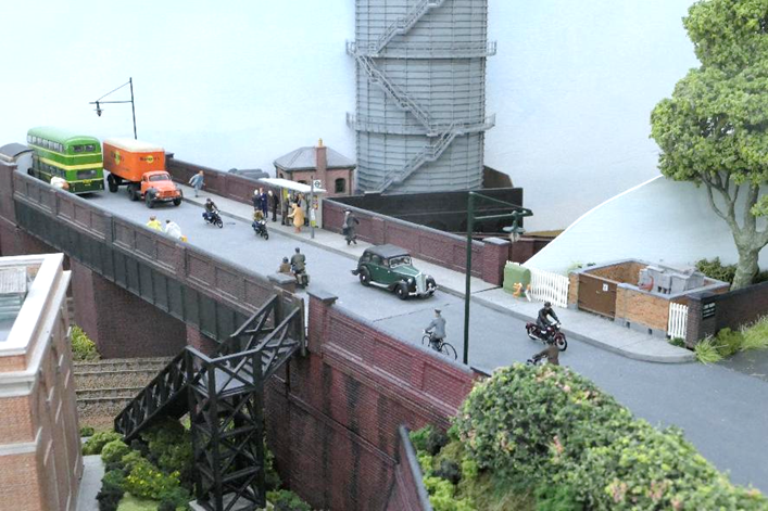
|
With the coming of the railway and associated development,
the previously tranquil Somersbury Lane became a
relatively busy street with its overbridge crossing both the Portsmouth main
line and branch to Cranleigh at the country end of Ewhurst Green station. In addition, a gas-holder (with gas supplied from
Cranleigh gas works) became necessary (the Cranleigh branch is just visible
in the foreground). Far from the lane’s rural setting, cycles,
motor-cycles and motor vehicles cross the bridge as passengers wait for an
omnibus. |
Local Industry
With the coming of the railway, it is entirely
credible that a limited amount of industry would have been located close to the
station in what is essentially a rural area. However, it is worth recalling
that Sussex and Surrey were once at the centre of England’s 15th-18th
century Iron Ore industry (many large hammer ponds still survive today although
the Wealden Forest is long gone), chalk pits, lime kilns, pottery, glass
industry and brickworks were once common industries alongside agriculture
(including wool and forestry).
Besides the 20th century brick and tile
manufacturing (just a short distance away on Horsham Road [Horsham Lane
becomes Horsham Road] just south of Walliswood
and at other nearby locations such as at Warnham) there are also other modern
rural industries such as the once-huge mushroom-growing facilities that once
dwarfed the village of Thakenham in Sussex.
In addition, there was post-Second World War
aircraft development at Dunsfold Airfield interrupting the seemingly rural
tranquillity.
A warm, dry and still day was needed to prepare the
retaining wall including weathering it's engineering brick; this being needed
to be undertaken outside and over its entire length to ensure a consistent
finish throughout.
|
With her striking white whiskers, Somer the Tuxedo cat undertakes an inspection of both the
pedestrians and motor traffic crossing Somersbury
Lane bridge. Here the railway’s Cathedral sub-station
has yet to be put in place. |
North-light Works
After the brick retaining wall was fixed in
position, north-light industrial buildings were placed above. In terms of
railway history, the factory originally stood atop a cutting and (withing the enlargement
of the station) the cutting had to be replaced with a retaining wall in order
to enable a headshunt alongside the Down Main.
This single-storey north-light works or factory is
deliberately non-descript and with Ewhurst Green being a rural area, conjecture
may suggest it is perhaps agricultural or brick /tile-manufacture related; its
location having been chosen because of the railway. The north-light is
deliberately long. However, in reality as an industrial building it isn’t
that large and is in keeping with what could be expected from a single-story
industrial building in an otherwise relatively rural area.
|
Above the headshunt with its LBSCR buffer stop
are offices. With an Aldershot & District Dennis Lowline at the bus stop,
Ewhurst Green’s solitary gasholder can be seen overshadowing Somersbury Lane overbridge. |
Commercial Building and Gas Holder
Alongside the north-light works is a post-war
(relatively new) two-storey low-relief commercial building (perhaps with
offices above). This building fabricated using window components from an
American H0 kit and although appears large, is relatively modest in size.
Beyond the Somersbury
Lane overbridge is a gas holder, needed to the increasing demand for town gas
at Ewhurst Green and the surrounding area; Cranleigh already having had its own
gasworks (founded in 1876) using water-sealed column-guided rising gas holders.
Supplied from this gas works (located next to Cranleigh station), Ewhurst
Green’s subsequent gas holder was of a post-Great War dry-seal type. Its
position belies the size of this potentially under-sized structure.
In reality there was no such industry at Ewhurst
Green, but neither was there a railway station and junction. However, there
were (for example) rail-connected brickworks in the area along with chalk pits
at the base of the North Downs. Cranleigh did have a gas works, and it appears
the gas holder was struck by a doodlebug V1 flying bomb in the second-half of
1944.
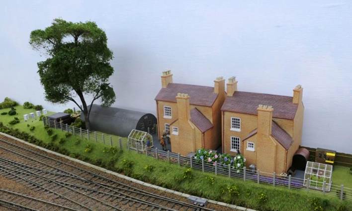
|
Two cottages back onto the railway - a dustman
talks to a gardener as removes the dustbin while a housewife cleans the
windows. At the second cottage and hidden behind some Hydrangeas, the yard is
being swept. An Anderson shelter and Pidgeon loft can be seen
behind the right-hand cottage’s greenhouse. During the war, a Nissen hut was squeezed in
alongside the cottages - beyond rabbits play around some lineside bee-hives. |
Lineside Housing & Structures
In the shadow of
the works (prior to the end of the Down Bay platform) a pair of cottages back
onto the railway. This pair of cottages were actually marketed by Bachmann
as a Georgian town house (44-077). However, from the rear their appearance was suitable
for cottages. Remember, from the railway’s perspective the rear of
properties is usually seen. For those who wonder what the front of these
Georgian houses looks like need only to look towards Lavender House by the
level crossing!
Several years ago,
a pair of aluminium greenhouses were produced by Bachmann (44-515), and it
didn’t take long to alter these to wooden-framed period buildings to sit
in back gardens each with white framing and different glazing arrangements. One
greenhouse now has an opening door - the other a sliding door.
Bachmann also
produced some delightful concrete domestic coal bunkers (44-538).
Hornby produced
model Anderson shelters (R8987) designed to be
part-buried and covered in soil, some were simply erected as sheds. Unit Models
produced the delightful Pidgeon loft (sadly this small firm appears to have
ceased trading but some of its range has been taken on by Frizinghall Models and Railways).
|
Next door to the cottages, soldiers deal with a
delivered-load at the MoD’s Nissen Hut (which was protected by an
ROF-type Pill Box now fenced in). |
Nissen Hut
Designed during the Great War and UK
patented in 1916, the Nissen Hut was named after its inventor, British Army
engineer Major Peter Nissen. Predominantly constructed of corrugated iron with
timber ends, many were quickly built during the second Word War.
Presumably intended
to give a degree of protection for the Nissen Hut and nearby Agricultural
factory, a square brick-built ROF-type (Royal Ordnance Factory) Pill Box was
located beside the Nissen Hut (44-110).
|
Type-24 concrete Pill Box (Wills kit SS74) The farm field beyond the fence is to |
The brick-built
ROF-type Pill Box compares to the nearby larger irregular hexagonal type-24
concrete Pill Box (the most common type in the UK) situated on the top of the
cutting overlooking the station platforms and goods loops beyond.
Chapter Twenty-Two

|
At the Horsham Lane level crossing one of the
railway’s three-wheeled Scammell Mechanical Horse queues behind a black
Mk1 Ford Consul. |
22. Rubber-Tyred Vehicles
Commercial Vehicles
Another scenic area
are road vehicles of which there is anow good selection available; particularly
Classix, Oxford and Base Models. Before the advent of these proprietary models
modellers could choose from kits such as the excellent Canterbury Commercial
kits (produced by the late John Janus) these can still be found from time to
time.
A mixture of
kit-built and proprietary vehicles appear on Ewhurst Green with those vehicles
selected for use being correct for the model’s time period and
(particularly in the case of commercial vehicles) meaningful including
geographically. There are a couple of firms that produce decals for commercial
vehicles including the sides of pantechnicons; these can make a huge difference
to (say) an otherwise plain Base model. Of course, this is not to say an
out-of-district lorry shouldn’t be present.
The Classix Ford
300E Singer sewing machine van is absolutely delightful and the Oxford Reliant
three-wheeled tricycle van charming; this pre-dating the glass-fibre bodied
vehicles. Oxford Diecast produced a Wales & Edwards milk float and space
for one of these with milkman out delivering on his round was made in front of
Lavender House (I believe this style of float was produced from 1955 to 1958).
|
Scammell Mechanical Horse Glen Woods |
Railway Commercial Vehicles
Both Classix and
Oxford Diecast produced a significant number of railway commercial vehicles
including the Jen-Tugs, the electric Jen-Helec and Scammell tugs (friend Ian
remembers these from his past-employment). There is also the Austin J2, K2
& K8 commercials, Ford E83W, 300E, 400E Thames vans & ET6 trucks along
with the Morris J-type (of which I have fond memories). Far more variations
available than would ever have been seen at Ewhurst Green.
Would Ewhurst Green
have seen a mechanical horse in operation? - very unlikely given its semi-rural
location. However, historical accuracy has been stretched particularly with a
nice kit-built Scammell tug and trailers; one with a load of three large timber
barrels.
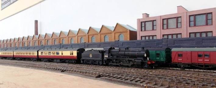
|
A cyclist is overtaken by a motorcyclist. |
Bicycles & Motorcycles
Czech Master
manufacture some rather nice kits of cyclists (albeit at 1/72 scale) which have
been completed and painted by Pete Goss for Ewhurst Green.
P&D Marsh
produce painted fifties motorcyclists of which many adorn the layout along with
an AA patrol man on his combination.
Oxford Diecast also
made a riderless combination in (at least) black (Police), khaki (Army), blue
(RAC), yellow (AA) and red (Royal Mail). One of the khaki combinations
(complete with panniers) was repainted and equipped with a P&D Marsh rider
and Bachmann (coach /bus) passenger seated in the sidecar behind a fly screen.
Private Cars
Both Classix and
Oxford Diecast have made a huge range of cars, so the choice is immense with
the ability to change models on the layout in order to maintain interest.
A green Wolseley 18/85 (Oxford) and white Morris
Minor convertible with its top down (Classix) have been placed on the layout - fitted
with drivers and passenger. A Triumph Herald with its bonnet open is receiving
attention at the village garage.
In respect of the
motor cars proffered the Classix Mk1 Ford Consul (EOTA) is rather nice, as is
their Morris Traveller - having owned an Almond Green Traveller (albeit with
tuned-up and bored out Mini-Cooper engine, overdrive and vented disc brakes)
I could not resist.
The Austin A30, A35
& A40 Devon are all exquisite with two types of Austin Seven appearing in
the form of the 1930’s version and Sir Alec Issigonis 1959 car
(Austin Super Seven with an equivalent Morris Mini-Minor) which were rapidly
rebranded the Mini; now a Riley Elf is produced (albeit the 1966 Mk3 version -
the 1961 Mk1 having external door hinges).
Besides these, the
many Fords, Standard Vanguards, Triumph Mayflowers and Vauxhall Wyverns are all
typical cars from the period although one of my favourites is the Citroen DS19
(remember seeing so many of these on Parisian streets whilst over there
riding on the last of the Sprague stock many decades ago), another is the
Jowett Javelin having always hankered after a Bradford Jowett van.
If only Oxford were
to produce an F-type Vauxhall Victor and a Mk E or F Bond Minicar….
Omnibuses
Being close to
Cranleigh the bus service would most likely have been operated by Aldershot
& District. However, it is plausible that their tentacles spread just a
little further to a potentially significant station such as Ewhurst Green.
London
Transport’s Greenline may also have permeated down from Dorking and
Southdown (who only reached as far north as Horsham) may have introduced a
service to a well-connected Ewhurst Green station. In any event bus shelters
have been positioned beside and on Somersbury Lane
overbridge with Aldershot and District services looping around in one
direction, Greenline in the other.
A concrete bus shelter sits just beyond the bridge;
a lightweight metal structure is on the bridge.
Although there are
many London Transport and Southdown model buses out there, Aldershot &
District are rare. Fortunately, luck provided a mint Aldershot & District
Dennis Loline 111 at a reasonable price (due to a
missing box wrapper). Whilst the Loline 111
didn’t enter service until December 1962 it would suffice, being close to
the Loline 11.
Chapter Twenty-Three
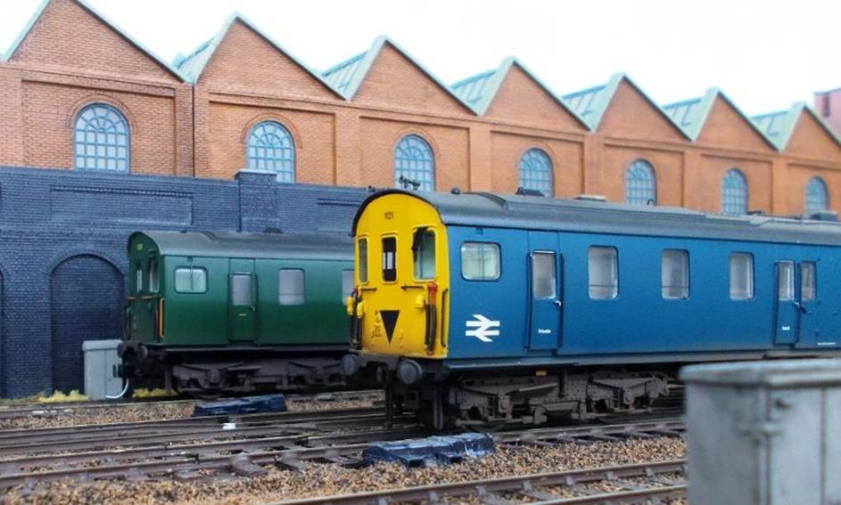
|
The rear of Ewhurst Green’s Art Deco Type 13 signal box. All the doors have been repainted and a notice
board added outside the entry-door opposite where a staff foot-crossing will
be sited into the Up side yard. The window frames still need to be repainted
brown. |
23. Signal Boxes and Signalling
Signal Boxes
Ewhurst Green has two signal boxes. Since its
pre-war re-signalling, the station has been controlled by an Art Deco Type 13 signal box (Bachmann
44-064) similar to Templecombe, Bognor Regis etc. This includes the
just-out-of-sight junction where the branch to Horsham leaves the Ewhurst Green
to Dorking main line. When time permits its box-floor window frames will need
to be repainted in the correct shade of brown although nameplates have now been
added.
Notwithstanding, the ex. LBSCR signal box (Hornby
Horsted Keynes R8955) is retained to operate the Mackenzie and Holland gates of
the Horsham Lane level crossing with (as a consequence) a number of signals
slotted. The signalman (crossing keeper) having excellent visibility of
approaching rubber-tyred vehicles on Horsham Lane.
Plumpton was one example of a mechanical signal box
being retained to
control the (Mackenzie and Holland) level crossing gates on Station Road.
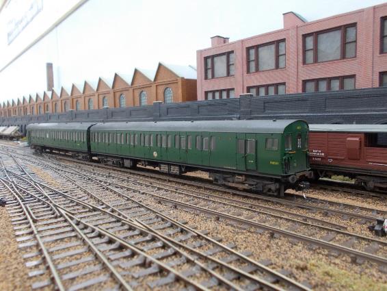
|
Just beyond the coal yard is Ewhurst
Green’s ex. LBSCR
London-end signal box; this having been retained to operate the gates on
Horsham Road level crossing. |
Signals
Some readers may find this section rather technical
(my apologies and please do skip to the next chapter) – hopefully many will consider it as being
informative although I have assumed a degree of knowledge on railway mechanical
signalling and its principles.
Ewhurst Green requires several scenically-visible
running signals (all platform Starting Signals) with all others (Distant, Home
and Advanced Starters) being located beyond the layout’s scenic section.
For example, a Home signal is typically 440 yards (overlap) out from the
station; the Distant signal typically being 1¼ mile beyond. However, the
wiring still requires an operating lever for the Home and Advanced Starting
Signals. Similarly while the subsidiary disc signals are non-functioning, each
still needs to function electrically from the electric lever frame.
London-end
Although the London-end junction to Dorking (main)
and Horsham (branch) is just out of sight (being just around the curve beyond
the level crossing), the correct aspect still needs to be shewn on the Up
starting signals for platforms 3 & 4.
Platform 3 Up Main starting signal.
> Main aspect Dorking.
> Secondary
aspect Horsham.
Platform 4 Passenger Loop Up starting signal.
> Main aspect Dorking.
> Secondary
aspect Horsham.
Country-end
The Country-end junction to Havant (main) and
Guildford (branch) is modelled as part of the scenic section. The Down
direction requires two right-hand bracket Starting Signals (platforms 2 &
4) and one Starting Signal (platform 1) with mechanical route indicator for the
main line to Havant and branch to Guildford:
Platform 1 Down Bay starting signal.
> Route indicator to Main & Branch.
> subsidiary signal into headshunt.
Platform 2 Down Main starting signal.
> Main aspect Havant.
> Secondary
aspect Guildford.
Platform 4 Passenger Loop Down starting signal.
> Main aspect Havant.
> Secondary aspect Guildford.
> subsidiary signal routes into headshunt and electric siding.
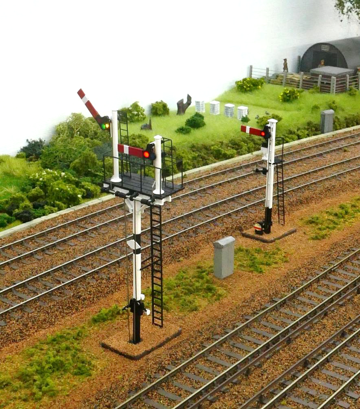
|
Both the Down Main and Down Bay Starting signals
have a route onto the Cranleigh branch; the bay signal being in the form of a
mechanical route indicator below its illuminated red lamp. This signal also
has a shunting signal at its base for movements into the headshunt. The bracket signal is displaying a Rule 55
exemption plate. |
Dapol Semaphore Signals
Dapol’s semaphore signals are used although at present
only single-route signal Stop signals and Distant signals have been produced
for Southern modellers. As an interim measure Dapol
LMS junction signals (T-brackets) are being employed. As this design was
perpetuated by BR, examples could be found on the Southern Region although in
general T-bracket signals were less common on the Southern than offset bracket
signals.
It could be argued that the use of bracket signals
adds to the appearance of the layout although my preference of ‘less is more’ remains. However, in this
case shear practicality won.
For the Down Bay Starting Signal (Platform 1) a
SR-design rail-built signal is used, this having been additionally equipped
with mechanical route indicator and subsidiary signal for the route into the
headshunt. The non-functioning route indicator was made using parts from a
full-disc subsidiary signal.
A second SR single post signal for platform 4 (Down
direction) was also considered but the setting up and adjustment of the relay
circuitry needed for reliable operation of these signals is problematic when
compared to the simplicity required for the bracket signals.
The instructions with the Dapol
signals state they should operate at 16v AC. However, subsequent instruction
sheets reduce this to 14v AC or 12v DC (even a 9v PP3 battery is suggested). So
a dedicated smoothed 9.5v DC supply was prepared and successfully trialled with
momentary contact operation needed to alter the single signal’s aspect;
this being achieved through the use of make-before-break contacts on a slugged
9slow acting) relay. By comparison Dapol’s
junction (bracket) signal can be operated with simple switched (changeover)
contacts.

|
Above - the mounted signalling relays (laid on their back). Front row far left is the armature slugged relay
for Platform 1 Starting Signal with the rheostat adjustment in the otherwise
empty relay bay in front of the black (pre-war) relay that repeats the
position of the Dorking /Horsham junction for the Up Starting Signals. Below – the terminations for the mounted
relays. Much pre-wiring is undertaken on the bench with
the visible straggling wires having been used to electrically bench-test each
circuit. Most of the relays were purchased (unused) over four decades
ago. |
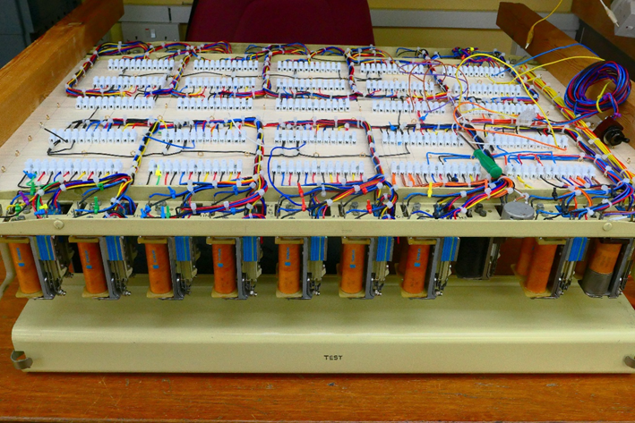
Signalling Relays and their Mounting Cases
Thirty relays are used directly to operate the
signals with another nine relays forming part of the conditional locking
circuitry. To mount the relays which control the running signals, two ex.GPO metal cases were used (each supports twenty relays)
with a termination board mounted in between; this comprising 25 no. terminal
bocks providing a total of 300 terminations. This might sound huge but the
wiring from the relays required 288 terminations.
On the reverse side of the termination board, 35
no. terminal blocks (providing a total of 420 terminations) were fitted on the
board between the two casing lids. These are there to terminate the wiring from
the electric lever frame; each lever switch having two sets of changeover
switches (6 wires). A number of turnouts will also be terminated here. However,
if some of the terminations aren’t required then surplus terminal blocks
can be removed (this being easier than trying to add more).
Each relay is overhauled (cleaning, testing and any
adjustments that may be required) before fitting followed by bench testing of
the pre-wired circuits. Each of the signalling circuits are identical in terms
of their wiring and the standardisation of colours used for the relay wiring.
In the interest of convenience, coloured cable tags are used to visually group
together each signal’s relays.
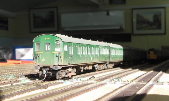
|
Ex. GPO 24v type 3000 heel ‘slugged’
relay (800Ω). |
Single Post Signal (Platform 1)
Platform one’s Dapol
single post signal aspect is changed by a momentary make-contact which needed
to be enabled using relays - many modellers just use a sprung push button which
was not compatible with Ewhurst Green’s (electric) lever frame. In terms
of relay control, providing a momentary contact isn’t straightforward;
even more so then that momentary contact has to be a fraction longer than
instantaneous.
A solution was found through the use of a slugged
(slow-acting) type 3000 ex. GPO relay. Operating on a smoothed constant 12v to
help slow its action, this relay is equipped with platinum-tipped
Make-Before-Break changeover contacts (the wires from the signal being
connected across the outside terminals) so when the relay operates, the two
wires are momentarily connected – just long enough to change the signal
aspect.
Even then, to ensure the duration of the momentary
contact is long enough, a rheostat was required to finely adjust the
voltage operation of the 500Ω
armature-slugged relay in activating (toggling) the Dapol
signal; the optimum activation voltage for this relay being around 7v.
Bench testing identified this adjustment
arrangement would be needed for each single post signal employed.
In total four ‘ordinary’ 24v/400Ω
type 3000 relays (with a fifth for the subsidiary signal) plus the single 12v
type 3000 slugged relay are required to operate this single arm signal.
It is worth noting that on Ewhurst Green model
railway, 24v is used as the standard operating voltage for ex.GPO
type relays on the layout.
Lest the signal ever does get out of
correspondence, a push-button reset button was considered. However, the simpler
solution is just to take the cover off the relay case and manually reset by
pressing the relay’s armature – being top left it is easily
identified.
The relays for this single arm signal are as
follows:
(1) Signal Normal Relay (to display a
‘Stop’ aspect).
(2) Signal Reverse Relay (to display a
‘Proceed’ aspect).
(3) Signal Slugged Relay (toggles the
signal’s aspect).
(4) Signal Locking Main Relay.
(5) Signal Locking Subsidiary Relay (route into
headshunt).
The Signal Locking Main Relay and Signal Locking
Subsidiary Relays prevent a ‘Proceed’ main or subsidiary aspect
from shewing if the route isn’t set or a conflicting route has been set.
Energisation of the Signal Slugged Relay changes
the signal aspect after which the relay remains energised until the next aspect
change occurs. In order to accomplish this, separate Signal Normal Relay and
Signal Reverse Relays are required in order to break a latched circuit (leading
to a change in the signal’s aspect).
In addition, when the layout is energised at the
start of each running session, the normally-energised type 3000 slugged relay
will operate meaning the single-post signal will undergo an unwanted aspect
change. To prevent this from happening, delayed switching is built into the
9.5v signalling supply meaning this 9.5v supply will only power-up after the
type 3000 Signal Slugged Relay has been energised during start-up. Having tried
some electronic delay relays (all faulty as none had the advertised
adjustment) the delay was simply achieved through the use of a daisy-chain
of spare heel-slugged 24v type-3000 relays.
Junction Signals (Platforms 2, 3 & 4)
Wiring for the Dapol
bracket signals is somewhat simpler as each aspect is switched by a simple
changeover switch. However, at least four relays are still required including
the obligatory Signal Locking Relay. These 400Ω relays are as follows:
(1) Signal Main Relay (control’s Main
aspect).
(2) Signal Branch Relay (controls Secondary
‘Branch’ aspect).
(3) Aspect Display Relay (switches the single lever
between Main & Secondary aspect).
(4) Signal Locking Main Relay.
and additionally for Platform 4 (Down direction
signal only):
(5) Signal Locking Subsidiary Relay (routes into
headshunt and electric siding).
The Signal Locking Main Relay and Signal Locking
Subsidiary Relays prevent a ‘Proceed’ main or subsidiary aspect
from shewing if the route isn’t set or a conflicting route has been set.
There has to be a degree of compromise with a model
railway’s (electric) lever frame combining the signal aspects on one post
to be operated by one lever. A similar arrangement does exist in some
12”=1’ railway signal boxes including Horsted Keynes on the
Bluebell Railway.
The Aspect Display Relays are fed from each of the
junction’s turnouts and selects either the Main or Secondary aspect as
appropriate. Separate relays are used to switch each of the signals Main and
Secondary aspects to ensure each aspect is placed at ‘Stop’ before
another aspect can be displayed (and for when the system powers down).
Only one Aspect Display Relay is required for the
both Platform 3 and 4’s Up Starting signals. This is on the basis only
one Up Starting Signal can only show a ‘Proceed’ aspect at any
given point in time and that the Main or Branch aspect arm for both signals is
selected by the same turnout. From the junction turnout a repeater relay is fed
from the Storage Loops relays as these are powered from a different 24v power
supply.
In searching around for a suitable low current
relay, a grubby black relay was found – something I’d purchased
over five decades ago just after decimalisation. It worked perfectly so was
given a complete overhaul during which it was identified by a good friend and
ex. GPO employee as being a pre-war example.
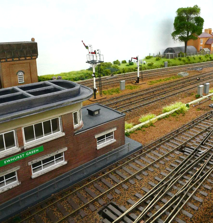
|
Down Main and Down Bay Starting signals located
directly opposite Ewhurst Green’s signal box. |
The 9.5v DC signalling supply was installed
adjacent to the cabinet containing the Mercury Displacement Relays with
dedicated sheathed cables out to each of the signal locations, This kept the
9.5v cabling visibly separate from the layout’s 12 /24v and 50v DC
circuits.
The first two signals to be installed were the
starting signals for the Down Bay (platform 1) and Down Main (platform 2);
these being in a part of the layout where the scenery was essentially complete
with no further works planned. The shunting signals in this area had already
been installed.
With the pre-requisite holes drilled through the
baseboard, the signals were set in position enabling the surround ground
scenery to be put in place before being temporarily removed so they
didn’t accidentally become glued in place with the ground scenery (lest
they needed to be removed for maintenance).
The signals are pre-mounted on a plastic base which
despite being part buried remains visible. At some stage the ground needs to be
raised around the signal’s base whilst be mindful the signal needs to be
easily removed for maintenance or replacement.
Although the layout’s mechanical subsidiary
signals don’t function mechanically, they do operate electrically (each
having their own lever on the lever frame) and form part of the station’s
control system.
Wiring of all the signals into the station’s
control system (conditional locking) was a whole challenge in itself although
used fairly simple relay-controlled circuitry developed for my previous layout,
Apothecary Street.
Colour Light alternative
As a backup measure some 4-aspect colour light
signals (with RH route indicator – nicknamed ‘feathers’) had
previously been acquired lest they be needed instead of mechanical signalling.
While 4-aspect signalling would probably have been unlikely for this location,
much of my railway career spent working in 4-aspect territory so these were
selected as an alternative for this busy location.
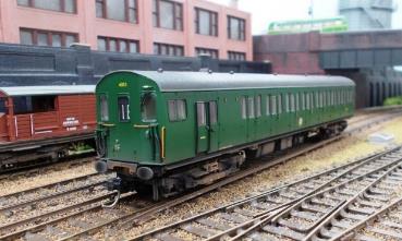
|
20mph Speed Board (right divergence) The junction off the Main line to the Cranleigh
Branch has a 20mph Permanent Speed Restriction. The speed at this junction being
dictated by both track geometry and in the Up direction a conductor-rail ride
ramp; these ramps having a 20mph speed restriction thereon. Behind is an
SR-allocated lined maroon GUV; a 2 EPB to the right. |
Speed Boards
In 1949 the Railway Executive recommended permanent
speed restrictions should be marked at the lineside that indication signs be provided on
the lineside at the commencement of restriction at places (1) where there are
no landmarks to identify positions and (2) where there has been experience of
persistent excessive speeds .
However, only a number of illuminated signs were installed at
very specific locations. On the Southern Region these were designated by a
commencement board (triangle) and a termination (‘T’) sign.
Following the Ministry of Transport's report into the fatal Sutton Coldfield derailment on 23rd
January 1955 (where a 60mph train derailed on a 30mph curve) British Railways reconsidered the
provision of speed restriction sign and in 1957 it decided to adopt the ex-LNER
system across the whole network. This system comprised lineside pole-mounted,
white-painted cut-out numbers.
Subsequent to the 1962-1963 big freeze
the further decision was made to paint the white numerals yellow in order to
improve their visibility in snowy conditions. The rear of the speed boards
remained black so as not to distract other drivers.
Ewhurst Green has a number of
Down-direction signed speed restrictions:
25mph (with direction arrow) into the
Up Loop (Platform 1).
20mph (with direction arrow) onto the
Cranleigh branch.
70mph (Down Main) from Somersbury Lane overbridge.
35mph (Down Branch) from Somersbury Lane overbridge.
There will
also be a 10mph (with direction arrow) from the Up Main across the single-slip
into Up Loop (Platform
1).
Chapter Twenty-Four
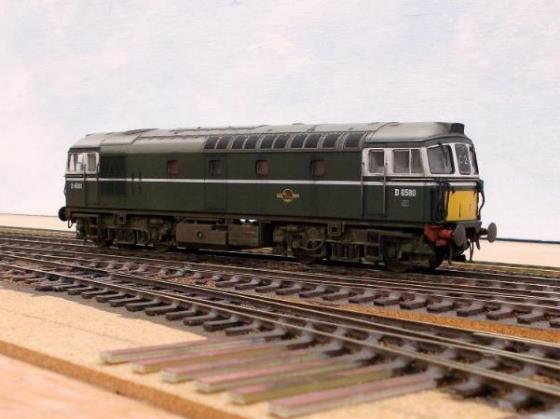
|
4 CEP no.7146 approaches Ewhurst Green on an Up
service whilst 2 HAP unit no.6008 (Phase ‘1’ /Batch
‘1’) passes on the rear of a six-car Down train. Both are Bachmann models expertly renumbered and
weathered by TMC. The 2 HAP was converted from a batch 2 model (roof lighting conduits
and underfloor control gear from 1957 to 1951-type); the 4 CEP unit carried
its experimental vertical warning panel for three years from January 1962
until 8th December 1966 when it entered Eastleigh for repainting;
becoming the last 4 CEP unit to carry plain blue livery. |
I have already covered my decision to remain with 00 instead of moving to EM or P4 had I been starting from scratch then I would probably have considered 3mm Southern Electric or even LBSCR elevated (overhead) electrics!
Wheelsets
Most of my rolling stock has had its wheelsets
replaced using wheels from Jackson (now Romford manufactured by Markits) or Ultrascale or Alan Gibson; these having a
14.6mm back-to-back dimension. Even though there are no plastic wheelsets in
use it is still surprising just how dirty the track gets after a day’s
running.
Some ready-to-run and all the kit-built steam
locomotives use Romford wheelsets as manufactured by Markits.
These are simple and straightforward to use giving excellent running.
Previously sold under the Jackson brand, coaches are usually re-wheeled with
14mm Romford wheels; wagons with 12mm. Hornby coaches use a slightly short axle
and have deep flanges accord Ultrascale wheels are used.
However, the diesel locomotives such as Heljan’s KA & KA-1A (class 33/0 & 33/2) and
Hornby JA (class 73/0) use Ultrascale’s
excellent conversion sets produced by Gear Services (Letchworth) Ltd. Whilst Ultrascale orders can have a
long lead time in production it must be remembered that this is a high-quality
bespoke specialist engineering service and the final high-quality product is
well worth the wait.
The superb Hornby HA electric locomotives (class 71
in modern ‘TOPS’ parlance) are having their driving wheels replaced
as their Hornby wheels appear to quickly attract the dirt; this is quick and
simple to do. The Hornby models are excellent runners with a considerable
haulage capacity in excess of a (then) competing model.
Couplings
In building my previous layout I spent considerable
time looking into the subject of couplings; eventually settling on the current
mini-coupling as used by today’s manufacturers. These are simple, easy to
fit (a wire bar is compatible) and today’s standard coupling amongst
manufacturers. However, in terms of the many coupling types out there my
favourite was the Winterley automatic coupling
although I’d always liked the operation of the Hornby-Dublo pseudo
buckeye.
In my opinion simple and reliable couplings are
prerequisites for a reliable operating layout. It is acknowledged that the
mini-couplings have their faults and limitations; they are certainly not pretty
but are practical and for the most, already fitted to proprietary stock. The
only significant fault with the mini-couplings is the difference in height that
sometimes occurs; particularly when some makes or models droop.
The exception to the use of mini-couplings is on
buckeye fitted stock where Kadee buckeye couplers were an obvious
choice; a choice that works well with buckeye fitted multiple units although in
terms of sheer practicality their use has been extended to other multiple-units
where the prototype had screw-couplings (for example 2 BIL, 2 HAL, 4 SUB &
4 LAV units); the use alternatives NEM-fitment couplings weren’t
successful although some Roco -types remain to be explored along
with Keen Systems couplings within sets.
The potential compromise of using Kadee buckeyes
with these Southern Railway-built units does enable closer coupling and an auto
uncoupling capability. For example, the Down Main, Up Passenger Loop and
electric siding have been equipped with a Kadee magnet to enable the division
of electric trains if the service pattered required it. These magnets can be
removed from underneath the baseboard if not needed.
It is worth noting a 2 BIL uses a Kadee no.19
whereas a 2 HAL uses no.20; the limiting factor being buffer-locking on the
36” Peco turnouts. Had the layout used Marcway
36” radius turnouts in the fiddle yard then one size lower could
have been employed. In terms of BR-design MU stock Kadee buckeyes
are used for all end couplers (2/4 EPB, 2/3H, 4 BEP, 4 CEP, MLV & TLV) once
the modelled Buckeye is eased out.
Kadee buckeyes are also used for the
intermediate couplings in corridor stock; again, sheer practicality along with
close-coupling being the deciding factor along with the ease of lifting coaches
off the track. The gangway air-gaps are closed and on Hornby’s Maunsell
corridor stock the opportunity is taken to retract the buffers enabling a mix
of Kadee No.17 and No.18. On non-corridor stock such as sets 152,
153, 154, 155 and 904 Bill Bedford couplings have been employed within sets;
these really do look the part although currently appear to be unobtainable.
When fitting Kadee couplings into NEM
sockets it is important to check the curved-steel actuating lever does not foul
the closure rails on turnouts or four-foot boards on crossings; those on
Bachmann multiple units need to be slightly adjusted upwards prior to fitting
(they are trimmed off within coaching sets).
However, the use of magnetic couplings is being
tried as these appear to function better where uncoupling is not requited.
Gangways
One of my bugbears is the air-gap between corridor
coaches and I’ve always sought to close these. Initially made my own
gangway in-fill bellows using folded black card fashioned in a scissors to expand
and compress. Subsequently found Modeller’s Mecca (in those days a
wonderful model shop which I strove to visit when driving to Manchester and
Fort William) supply these ready-made to fit (simple plug-in) a wide range
of coaches at a price that meant home-production simply wasn’t viable.
However, on close-coupled Mk1 sets bellows on both
coaches are too much but a single bellow can still catch the gangway. Modellers
Mecca were approached about producing a reasonable quantity of plug-in end
plates (i.e. minus bellows), but they chose not to respond so these are being
phased out as unsuitable.
As a consequence, Keen Systems floating end
plates were trialled on Bachmann Mk1 stock. These do work well although need to
be fitted carefully if precision is wanted; that is without sideways wobble.
However, this is easily achieved when fitting these; 20-thou plastic strips
were glued to the inside of the coach’s gangways reducing sideways play
in the end-plate. In terms of springing the fixing plate (this also serves as a
drilling jig) is placed external to the moulded end-door of the coach to serve
as a spacer thus giving the spring greater compression if required.
Further to this (and if trials are successful)
I’ll be looking at replacing the Bachmann coupling yoke /No.20 buckeyes
with the Keen replacement. Certainly, now looking to quickly equip all the 4 BEP /4
CEP stock with Keen Systems floating end plates. It is worth adding there is a significant amount
of information on the Keen Systems website in respect of fitting couplings.
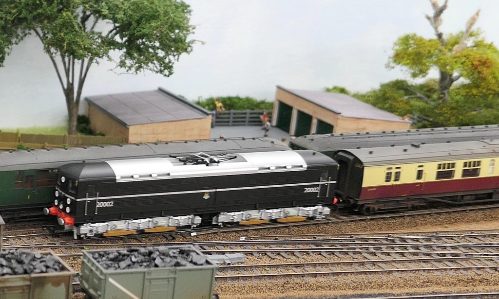
|
Friend bought across his Kernow 2H Hastings unit no.1122 across to have its first run; seen here
passing through part of the (then incomplete) fiddle yard. No.1122 has since
run with other 2H Hastings and Hampshire units of varying liveries! The 2H Hastings units (nos.1119 to 1122) were not equipped with
roof-mounted lighting conduit. However, from May 1974 unit no.1121 did have
roof-mounted lighting when its identity was swapped with unit no.1108.
Consequently, this unit has now been weathered and renumbered as unit no.1121
as a 2H Hastings unit was wanted. |
Modifying Heljan Locomotive-couplings
It is unfortunate that many Heljan
couplings have a tendency to droop with coupling engagement being poor and the
bottom of the hook-assembly catch the stock rail on S&C, leading to
derailments. Having tried (with limited success) gluing the hook and bar
assemblies onto the bogie frame a simpler solution was found through the use of
Bachman straight (rather than cranked couplings). It is worth saying on
36” minimum radii curves, the fixed (glued) coupling really didn’t
create any problems.
Modifying Bachmann Mk1 Coach-couplings
Like most coaches, the Bachmann Mk1 Corridor
Coaches benefit from close coupling; one immediate solution employs Kadee buckeyes.
However, other NEM-type plug-in coupling types exist such as Roco .
Keen Systems
Furthermore, Keen Systems replacement yokes
with fixed buckeyes are now being investigated and will be reported on in due
course. Initial results are really promising.
Coach Faults
On longer trains in particular (say twelve bogies),
certain coaches kept derailing as they entered the straight leg of Peco turnouts
off 36” curves in Ewhurst Green’s storage loops. After some
investigation the causes was found to be on the underside of the coaches with
no turnout fault. The two issues being:
|
(i) |
The NEM-style pockets are mounted on a yoke which
surrounds the bogie pivot being held back by a small spring. My replacement
wheelsets have much finer flanges and so had an increased propensity to
derail if the bogie rubs against the plastic hook that retained this small
spring to the underside of the coach. Careful paring down of the hook
eradicates the problem. |
|
(ii) |
As the coach transitions between the curve and
straight the yoke moves and one of the two lugs on the yoke slide forward across
the underside of the coach. Some coaches (the FK in particular) have a small
amount of plastic flash that catches on the yoke interrupting its smooth
movement; the resulting jerk causing a derailment under load. Simply removing
this flashing resolves the issue. |
Since then, Roger Keen (of Keen Systems) has
identified a further fault where an upper lug in the yoke can catch the
interior moulding of the coach - trimming the interior appears to solve this.
Kadee Buckeyes
When using no.20 Kadee buckeyes within
sets using Bachmann Mk1 stock, two easily corrected faults were found. The
shorter shanks on no.19 Kadee buckeyes foul the coach buffer beam
and when propelling the buffers come into contact. As these buffers are fixed,
they are difficult to retract (unlike Hornby’s Maunsell stock).
When using Kadee buckeyes within sets
there were instances of derailments on turnouts. The issue was rapidly located;
the steel actuating arm on Kadee buckeyes can sit low and catch the
stock-rail. On multiple-unit stock these are simply adjusted to provide more
clearance; within fixed coaching sets (which do not uncouple) the arms are
simply snipped off with heavy duty piano-wire cutters.
Magnetic Couplings
Magnetic couplings are currently being trialled
with initial results shewing great promise. They are even produced to resemble
buckeyes.
Changing Hornby Coach Wheels
Hornby coaches appear to have a slightly deeper
flange than Bachmann models with these deeper flanges contacting the sleeper
chairs on curves. In addition, on certain batches of coaches one of the wheels
is not a firm fit on its axle and can be prone to unwanted changes in its
back-to-back dimension (leading to derailments).
Accordingly, many Hornby coaches are having their
wheelsets replaced with 14mm Romford wheels with their back-to-back dimension
set to 14.75mm. Consequently, running of these sets is much improved and whilst
the cost of the 14mm disc wheel has significantly increased to £2.50
/axle in 2012 (around a decade previous they were 84p) the expense remains
worthwhile. The most recent changes of wheelset have employed Ultrascale
s excellent wheels.
In terms of running, the wheel-rail interface is
critical with guidance offered on the BloodandCustard websites.
Chapter Twenty-Five
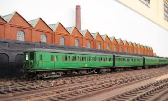
|
Oil train mainly formed of grubby Berry Wiggins
tankers heading out from Hoo Junction to Southampton trundling south through
Ewhurst Green. |
It would be boring to provide complete lists of
rolling stock some of which is kit built; others proprietary often with minor
modifications or additional detailing that can make a significant difference.
For example, it is surprising how many visitors struggle to identify
Bachmann’s N-class 31848 which appears in its short-lived 1955-1957 guise
without smoke deflectors.
However, some of the coaching sets and multiple
units are worthy of note so have been detailed.
Few modellers set a specific date for their model
although many operate to a period. At present Ewhurst Green is intended to
follow the latter; roughly between 1956 and 1961. However, in doing so whilst a
Sulzer type 2 (1958-built class 24) might just be seen hauling CLC liveried
Maunsell stock a type-KA Crompton (1960-built class 33) would simply look out
of place with these CLC liveried coaches (although very rare, they could be
seen with CLC liveried Mk1 3-sets).
Notwithstanding, a few models outside of this
period have crept in such as Brighton-built Bulleid diesel 10203 and a few
BR(S) emus with yellow warning panels (circa end of 1963-on).
Then of course some rolling stock has been
redeployed from elsewhere on the Southern Region being needed to operate the
Ewhurst Green services.
Chapter Twenty-Six
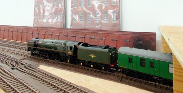
|
M7 no.30056 hauls ex.LSWR
3 LAV Cross-Country set 130. However, as two of these superb coaches actually
belong in set 131 a second weathered set with renumbered coaches was ordered
from TMC in order to create two correctly coach-numbered sets (130 &
131). |
26. Rolling Stock (Coaching Stock)
Overview
Research is often the key to modelling. For
example, coaches are correctly formed into the Southern Region’s
prototypical sets; something model manufacturers have only started to undertake
in the past two decades.
Southern’s use of Coach Sets
As a general overview, up to March 1966 the
Southern typically kept its coaches allocated into fixed formations usually
allocated to services within each Division. These sets could be strengthened
from a pool of Loose coaches and where a coaching set included catering
vehicles (including Pullman cars) these were not specifically allocated to each
set. If an issue befell an individual coach, it was normal practice for the set
to be sent to Lancing (sometimes Eastleigh) works for repair; sets usually
entered works for maintenance (including 2 yearly varnishing /10-yearly
painting) as one.
In service, mainline coaching sets usually had a
guard’s compartment at each end; the Southern did not normally operate
services with a swinger (coach without guard’s compartment) at its rear.
Arguably the most common mainline set formation was BTK-CK-BTK.
The operation of sets should underpin a Southern
steam layout as to the initiated eye, not to do so looks strange. All too often
at exhibitions a mainline Southern steam express can (in my opinion) often be
observed inaccurately portrayed with swingers (non-Guard braked coaches) at the
train’s rear and other coaches apparently randomly-mixed elsewhere.
However, there are always exceptions (particularly
entering the sixties) such as the London-bound Okehampton Car Carrier (which can be modelled on Ewhurst Green) with its
GUV vans (devoid of a Guard’s compartment) placed at the rear on the
London-bound return (only); in this case an operational necessity for the
service.
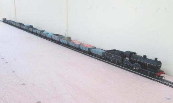
|
N-class no.31848 hauls ex.LSWR
3 LAV Cross-Country set 314 south through Ewhurst Green. |
Modelling of Coaching Sets
In terms of correctly modelling the
Southern’s numbered coaching sets, I believe this started with
Replica’s excellent correctly numbered BR(S) Exmouth branch 3-car
non-corridor sets in both Crimson Lake and Green liveries. Replica subsequently
went onto to produce a very limited number (just 3) of the remaining Oxted line
non-corridor vehicles used in set 904; soon after Hornby produced SWD Maunsell
Special Traffic set 273 in BR(S) green paired with Schools-class no.30924
Haileybury.
Now the production of SR-coaches in sets is
becoming the norm with the various pull-push sets, Bulleid Multidoor and
64’ sets. SECR Birdcage sets, 48’ LSWR Maunsell rebuilds,
EFE’s ex.LSWR 3 LAV sets and so on.
Many of these feature on Ewhurst Green including
Hornby’s Bulleid 59’ multidoor 3 Cor sets (particularly as some
sets worked around Horsham) followed by Bachmann’s Bulleid 64’ sets
which augment some of their earlier model coaches (now super-detailed and
flush-glazed).
Following trials with some LSWR gate-stock for the
pull-push services (set no.373 was actually used Guildford Bordon)
Hornby’s converted Maunsell sets were also welcome addition, particularly
as they have modelled both variants (with whistle or air-horns). Sets 607
(withdrawn after the Eastbourne station collision) and 619 are in service on
the layout.

|
Ex.LSWR 2 LAV set no.43 in faded Crimson Lake. |
Non-corridor Stock
These models were followed by Hornby’s
release of the Maunsell rebuilds of the LSWR 48’ coaches; in BR(S) days
these attained Crimson Lake livery with just a few of the seconds receiving
BR(S) Green livery. No.320 retained Southern Railway green (with BR typeface)
after nationalisation until it was repainted (BR green) at Lancing; being
outshopped 4th October 1956.
With Bachmann’s excellent Birdcage stock
there is little shortage of coaching stock for local services and EFE’s
absolutely superb ex.LSWR 3 LAV cross-country sets
have also been purchased (weathered by TMC) both in Crimson
Lake and post-war SR Green (with BR numbering).
The numbers on set 130 did not carry an S-suffix
which would date the model between outshopping in Crimson Lake on 15th
January 1951 until varnishing 5th December 1952. Unfortunately set
130 was produced with two incorrectly number coaches these belonging to set
131.
So, a further order was placed with TMC to create (and
weather) both sets 130 and 131 as follows:
This is what EFE
erroneously produced in their E86014 pack:
|
Set |
BTL |
CL |
BTL |
|
130 |
S2953 |
- |
- |
|
(131) |
- |
S5041 |
S2955 |
To correct set
130 plus create a new set 131, the following work was undertaken with the set
number on S2955 corrected to 131. As set 130 was modelled without post May 1951
S suffixes (set 130 would not have received these until outshopping on 5th
December 1952) and the post-nationalisation painting dates for set 131 was not
known (with Crimson Lake livery assumed), it was decided to leave set 131
without an S suffix.
|
Set |
BTL |
CL |
BTL |
|
130 |
S2953 |
S5040
|
S2983
|
|
131 |
S2954
|
S5041 |
S2955 |
At the same time a second Green-liveried 2 LAV set
312 with the spare BTL from this
set renumbered as DS1905 (Redhill Breakdown Train); this having been BTL 2959
from set 133.
These sets were
withdrawn (or reallocated) as follows:
|
Set |
|
Date |
|
|
43 |
17th
May 1958 |
||
|
46 |
1st
April 1959 |
||
|
130 |
6th
October 1956 |
||
|
131 |
11th
September 1954 |
||
|
154 |
(to
WR 29th December 1962) |
||
|
312 |
27th
October 1956 |
||
|
314 |
21st
June 1957 |
||
|
595 |
18th
July 1958 |
||
|
622 |
31st
March 1956 |
||
Non-Corridor Coaching Sets in Service
Weathered coaching sets currently in service
include:
|
43 |
Ex. LSWR 2 LAV
set in Crimson Lake livery. Coaches BT S2637 & BCL S6402. Withdrawn 17th
May 1958. Running strengthened with Loose TL. |
|
46 |
Ex. LSWR 2 LAV
set in Crimson Lake livery. Coaches BT S2420 & BCL S6405. Withdrawn as a
five-coach set 1st April 1959 (three SECR 100-seaters had been
inserted into the 2 LAV set for the 9th June 1958 CWNA). |
|
130 |
Ex. LSWR 3 LAV
set in Crimson Lake livery (15th
January 1951 to 5th December 1952). Coaches BTL S2935, CL S5040
& BTL S2983. Withdrawn at Lancing 6th October 1956. |
|
131 |
Ex. LSWR 3 LAV
set in Crimson Lake livery. Coaches BTL S2954, CL S5041 & BTL S2955. Withdrawn at Lancing 11th September 1954. |
|
154 |
BR Mk1 non-corridor Exmouth branch set in post-20th
October 1960 Green livery. Coaches BT S43378, C 41062 & S43379. Set
transferred to WR 29th December 1962 and withdrawn during 1964. |
|
312 |
Ex. LSWR 2 LAV
set in Green livery. Shortened to 2
LAV late 1946 with BTL 2946 withdrawn 7th December 1946 so set formed CL S5062 & BTL S2947 Set withdrawn Lancing 27th
October 1956. The spare BTL
from this set was renumbered as DS1905 (Redhill breakdown train). |
|
314 |
Ex. LSWR 3 LAV set in Green livery. Painted 26th
June 1946 thence BR numbering applied during varnishing. Coaches BTL S2979,
CL S5043 & BTL S2981. As the last surviving set, its brake coaches were
withdrawn 21st June 157 with the composite on 14th
August 1957. |
|
595 |
Ex. SECR Birdcage
Trio C set in Crimson Lake livery. Coaches BT3428, CL 5469Ϯ & BTL 3499.
Withdrawn 18th July 1958. Ϯ Diag. 2315 |
|
622 |
Ex. SECR Birdcage
Trio C set in post-war Malachite Green livery (some sets carried this Green
through to at least 1956). . Coaches BT3455, CL 5484Ϯ & BTL 3527.
Withdrawn 31st March 1956. Ϯ Diag. 2315 |
|
Loose |
Ex. LSWR Maunsell rebuilds in Crimson Lake: BTL
S2627S, BTL S2629S, TL S267S & TL S280S. |
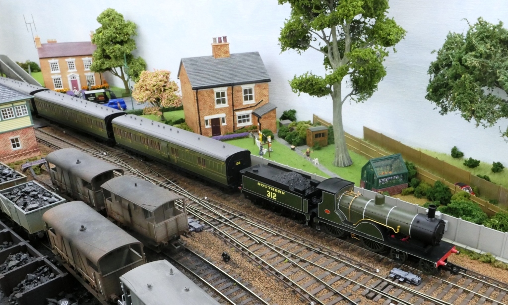
|
Ex.LSWR Pull-Push set no.735 in Crimson Lake livery. |
Pull-Push Sets
The Southern made good use of steam Pull-Push train
operation followed by the diesel /electric hauled /propelled 4 TC units used on
the Bournemouth Line electrification. Kernow arranged for the manufacture of
ex. LSWR gate stock (plus the 4TC electric units), and Hornby undertook the
Maunsell Pull-Push rebuilds of the late 1950s. Latterly EFE re-released the
Gate Stok sets 363, 373 & 374.
Although some of the ex. LSWR Pull-Push sets were allocated to both the
CED (731, 732, 733 & 737) and SED (736, 738 & 739), sets 734 & 735
remained on the SWD spending much of their lives as spare sets based at Exeter
Central.
Maunsell Pull-Push Set 607 was disbanded 15th September 1961 (following the Eastbourne collision and
the scrapping of its BCK). However, its SO (no. 1343) was repaired at Lancing Works (entering 21st November
1961 - outshopped 11th January 1962) thence to ‘Loose’
strengthening Lymington branch pull-push sets. In Ewhurst Green’s history
it also spent time strengthening set 619. When set 619 was disbanded its SO
also became ‘Loose’ in the dying days of the Southern’s
steam-propelled Pull-Push operations.
Push-Pull Sets in Service
Pull-push sets currently in service include:
|
373 |
Ex. LSWR Gate
Stock in Green livery. Outshopped SR Green 15th February 1946
thence CL livery 8th May 1951 and BR(S) Green 3rd July
1958. Set withdrawn 11th November 1960. |
|
374 |
Ex. LSWR Gate Stock in Crimson Lake livery (paint
date unknown but certainly early with the waist rail lining). Withdrawn
Lancing 14th July 1956. |
|
607 |
Maunsell Pull-push set in Green livery.
Outshopped 6th January 1960, set disbanded 15th September 1961 following
Eastbourne collision (BCK scrapped), SO to Loose (Lymington Branch). |
|
619 |
Maunsell Pull-push set in Green livery.
Outshopped 29th January 1960, set disbanded June 1963 with BCK
condemned and SO to loose Pull-Push use until withdrawal 31st?
October 1964. |
|
735 |
Ex. LSWR Pull-Push 2-set outshopped in Crimson
Lake livery 20th June 1951. Set scrapped January 1961. |
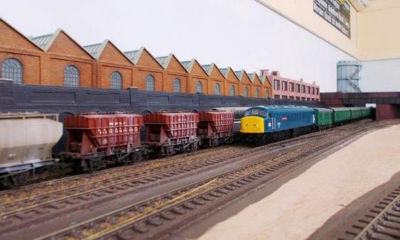
|
In its October 1955 to
February 1957 guise (without smoke deflectors), N-class no.31848 hauls
Bulleid multi-door set 963 away from Ewhurst Green. New from Eastleigh Works
14th March 1946 (post-War Malachite), set 963 was outshopped from
Lancing Works in CLC livery on 22nd October 1953 thence appears to
have gained BR(S) green livery on 14th September 1957. |
Corridor Stock
Liveries are also important with the corridor stock
(Bulleid, Maunsell and BR Mk1); these all being available in both Crimson Lake
& Cream (aka Blood & Custard) and BR(S) stock green (from July
1956-on). Some SR malachite; liveried stock survived at least until 1956 indeed
there are coaches that missed out crimson lake altogether. A concise history of
these liveries is covered at www.BloodandCustard.org.
In terms of the Southern Region’s Lancing
carriage works the last Crimson Lake & Cream (coded CLC) vehicle was
outshopped on 17th July 1956 (High Window Maunsell SK) with first
repainted from Crimson Lake & Cream into Green livery occurring the next
day (Bulleid SK). CLC did not suit Maunsell compartment stock and by 25th
March 1959 the last Maunsell corridor coach had been repainted into Green
livery although some Mk1 coaching sets remained in CLC right into 1963.
Whilst both Hornby and Bachmann produce Mk1
corridor coaches. Unfortunately, in terms of BR(S) Green livery Hornby choose
to incorrectly add carriage roundels to many of their versions thus precluding
their purchase for Ewhurst Green.
Deliveries of Bachman’s new Bulleid 64’
saloon stock were received and these sit well with Hornby’s Bulleid
59’ multidoor stock.
Corridor Coaching Sets in Service
Weathered coaching sets currently in service
include:
|
69 |
Bulleid ‘R’ 2 Cor set (BSK /BCK) in
BR(S) Green livery (outshopped from SR Green 18th January 1957) to
reformation in February 1963 when the BSK was replaced by SK S43S. |
|
179 |
Maunsell High Window 3 Cor set (6-compt. Brake coaches – BCK
S6673 /BTK S3732) in post 17th April 1956 Crimson Lake &
Cream livery. This set was subsequently outshopped in BR(S) Green-livery 8th August
1958. |
|
201 |
Maunsell High Window 3 Cor set (4-compt. Brake
coaches) in post 13th December 1954 Crimson Lake & Cream
livery. This set was subsequently outshopped in BR(S) Green-livery 27th
July 1956 before withdrawal in 1961. |
|
230 |
Maunsell High Window 3 Cor set (6-compt. Brake
coaches) outshopped from SR Green into BR(S) Green-livery 28th
February 1957 before withdrawal in 1962. |
|
242 |
Maunsell High Window 3 Cor set (6-compt. Brake
coaches) in post 8th April 1953 Crimson Lake & Cream livery.
This set was outshopped in BR(S) Green-livery 27th August 1957
before disbandment in June 1962. |
|
390 |
Maunsell Low Window 3 Cor set (4-compt. Brake
coaches) in Green-livery (CLC was carried 9th October 1953 to 17th
December 1957). |
|
399 |
Maunsell Low Window 3 Cor set (4-compt. Brake
coaches) in Green livery (CLC was not carried by this set). |
|
525 |
BR Mk1 3 Cor corridor set in Crimson Lake &
Cream livery (from new to when reformed 30th June 1959). |
|
781 |
Bulleid ‘L’ 3 Cor set in BR(S) livery (new 6th
March 1947 although livery from first varnish when Gill Sans typeface was
applied 24th April 1949) to BR(S) Green (believed during damage
repair to all three coaches 4th July 1957). |
|
790 |
Bulleid ‘L’ 3 Cor set in SR livery
(new 17th October 1947 to first varnish 13th January
1950 when Gill Sans typeface was applied). |
|
832 |
Bulleid ‘L’ 3 Cor set in CLC livery
(11th July 1952 when RH numbering applied to outshopping in BR(S)
Green on 7th February 1957). |
|
836 |
Bulleid ‘L’ 5 Cor set in CLC livery
(26th January 1953 when RH numbering applied to outshopping in
BR(S) Green on 6th May 1957). Set strengthened from 3-coach to 5-coach in
January 1953. |
|
847 |
Bulleid ‘L’ 5 Cor set in CLC livery
(new April 1950 to 27th February 1952 varnish and when RH
numbering was applied). Operating with Loose TK. |
|
963 |
Bulleid 59’ Multidoor 3 Cor set in CLC
livery (between 22nd October 1953 and 22nd August
1957). |
|
967 |
Bulleid 59’ Multidoor 3 Cor set in Green
livery (it was in CLC livery between 25th March 1955 and 4th
September 1957). |
|
968 |
Bulleid 59’ Multidoor 3 Cor set in Green
livery (it was in CLC livery between 11th December 1953 and 22nd
July 1957). |
|
972 |
Bulleid 59’ Multidoor 3 Cor set in Green
livery (this only one of four Multidoor' sets which never received CLC
livery). |
Non-Passenger Carrying Coaches
The layout has a number of non-passenger carrying
coaches; both four-wheeled and bogie stock. This mostly includes Bachmann,
Hornby and Dapol models in Green, Crimson Lake,
Crimson Lake & Cream and Maroon liveries.
Ewhurst Green also has a number of SR-numbered GUVs
which can be used to form a full-length Surbiton Okehampton Car-Carrying train
(in 1960 before repainting of the GUVs into BR(S) Green started taking place in
March 1961). Bachmann produced BR(S) Green liveried GUVs nos.S86724 (cat.
no.39-273), S86791 (cat. no.39-273A) and S86804 (cat. no.39-273Z);
the latter included Okehampton Car Carrier boards although the train
used paper labels as GUVs were not equipped with brackets for destination
boards.
However, as the Southern Region’s allocation
of GUVs had been delivered new in lined maroon (by October 1959) eight in this
livery were renumbered accordingly: S86708, S86739, S86745, S86752, S86787,
S86796, S86805 and S86834.
Two lined maroon BR Mk1 CCTs (including M94291
by Invicta Rail /Bachmann cat. no.39-550Z) are equipped with buckeye couplings on one end to
operate with MLVs; these being easily identifiable amongst all the other vans.
Chapter Twenty-Seven
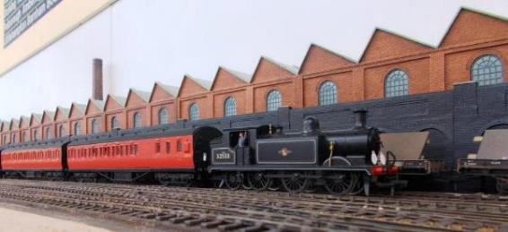
|
Visiting Kernow 2H Hastings unit no.1121. This model was weathered
& renumbered by TMC from no.1122 (which was not equipped with roof
lighting conduit). This is where it gets interesting for as-built no.1121 did
not have lighting conduit either, only gaining these when its identity was
swapped with no.1108 (sitting behind) in May 1974! |
27. Rolling Stock (Multiple Units)
Overview
For the most part
multiple units run in multiple with other units and Ewhurst Green was intended
to exploit this. However, it must also be remembered that when the 2H diesel-electric units were introduced they
were regularly operated singly. Similarly, the 2 SL electric units usually ran
singly. In comparison the 4DD units rarely operated singly after 1953 and (with
exceptions) the 5 BEL Brighton Belle electric units normally operated in pairs.
Multiple units often
intermixed with other compatible types such as 2 BIL & 2 HAL units and 2
HAP + 4 EPB formations. In terms of the BR 90mph units when mixed with 75mph at
least half the train must have been formed with 90mph units.
Diesel Electric Multiple Units
Kernow released the 2H DEMU units (2H Hampshire units were in number range
1101-1118; 2H Hastings 1119-1122) so these couldn’t be ignored.
Currently two weathered 2H units are in use.
No.1108 entered service on 9th September 1957. Its motorcoach was badly damaged in a collision with
light engine 30480 at Eastleigh w/e 6th May 1961 but repaired. It
was made up to a three-car on 10th October 1959 and yellow warning
panels were added 7th February 1964.
No.1115 gained its Orange Vee post-February 1960 (this denotes there is no
brake van at the other end of the unit) with its air-horns probably
fitted during 1963 and certainly by 3rd November 1963. Although
no.1115 was made up to a 3H on 12th August 1959 (before the Orange
Vee) and unit 1115 was not recorded as having its centre car removed late-1959
(some 3H units had their centre cars were randomly removed during winter 1960),
unit 1115 was running as a 2-car on 3rd November 1963 (with
Orange Vee, early blinds & air horns) before Orange Vee, later
blinds & air horns by 26th April 1964.
2H Hastings unit no.1121 is also planned as the
Bachmann (Kernow) model was erroneously equipped with roof-lighting conduit
which needs to be removed (the 2H Hastings units were not equipped). The DTC
has already been prepared by virtue of a simple roof-swap with the DTC of a 2
HAP (Phase 1) during the 2 HAP’s conversion from a Batch 2 to a Batch 1
unit. The motorcoach needs careful attention.
|
1108 |
2H Hampshire unit with early grills. Released
from Eastleigh 6th September 1957. MBS 60107 badly damaged in
collision with light engine 30480 at Eastleigh w/e 6th May 1961
but repaired. Yellow warning panels were added 7th February 1964. In May 1974 MBS 60107 & DTC 60807 both
exchanged with 60120 & 60820 (ex.2H no.1121) and units swapped
identities. |
|
1115 |
2H Hampshire unit with Orange Vee and air
horns but early blinds. Released from Eastleigh 5th October 1957
and made up to 3H from 12th August 1959. No.1115 had not yet
received an Orange Vee on 2nd February 1960 but was carrying one
on 3rd November 1963 (and into late 1966). Second-class compartment in DTC converted to
luggage space 13th July 1963. Unit recorded as running as a 2-car
3rd November 1963 and again 26th April 1964 on
Southampton Terminus to Alton services (with air horns) but the early blinds
appeared to have been replaced between these two dates. |
|
1121 |
In preparation having its roof-lighting conduit removed. 2H Hastings
unit with small warning panels and no roof lighting conduit. Released from
Eastleigh 14th June 1958. Yellow warning panels added 11th
June 1965. It is possible that as a 2H Hastings unit no.1121 was never
equipped with an Orange-Vee. AWS fitted and second-class compartment in DTC 60820 converted to
luggage space Jully 1967. In May 1974 unit made up to 3H by inclusion of TS 60657 (ex.1108) and
units swapped identities, the new no.1121 now formed of MBS 60107 &
DTC 60807. |
A couple of 3D Oxted units with one to possibly to
run with a 6-car Hastings unit (this formation used to run from Tunbridge Wells
West into London) - are also envisaged.
Although slightly out-of-era a 3R
‘Tadpole’ is planned in its green livery and without yellow warning
panel on the motorcoach for the single Sundays-only 13:54 semi-fast return
service from Reading General (pushing the mileage for fuel, this was in an
impossible-to-find addendum to CWN working no.145).
|
Close-up of 2 HAP unit
no.6008 (Phase 1 /Batch 1) passing 4 CEP unit no.7146 (with its experimental
post-January 1962 vertical yellow warning panel). 4 CEP units nos. 7133-on were outshopped new with UIC First-class
cantrail banding starting from end-January 1959. |
Mainline Electric Multiple Units
4 BEP /4 CEP /MLV
Bachmann produced its superb model of the 4 CEP
unit rapidly followed up by an MLV. 4 BEP (no.7005) is also on the layout;
ideal for the fast services although these often didn’t always feature in
lessor boat trains (as there were insufficient 4 BEP units for all).
Expertly weathered and renumbered by TMC, 4 CEP units
nos.7105, 7107, 7114, 7129, 7132, 7141 & 7146 run on the layout (sometimes
with MLV no.68001, 68002 or 68006). Besides running together as 8 or 12-car,
these 4 CEP units regularly run as 6 or 8-car formations with 2 HAP units -
sometimes up to twelve cars. The MLVs can sometimes be seen prototypically
hauling short van trains.
However, even though the Bachmann emu motor bogies
would appear to be identical they can often run erratically when running in
multiple particularly when four or more are coupled. This was found to be down
to different motor characteristics in the later models such as the 4 BEP units.
Accordingly two older model yellow warning panel 4
CEP units were selected for weathering with the intention of swapping their
motor bogies over with the 4 BEP units. The two yellow warning panel 4 CEP
units (7122 & 7126) would then only ever run together and would not be
paired with other units.
The choice of some MLV, 4 BEP & 4 CEP unit
numbers related to minor items of interest in their history:
|
68001 |
Completed 25th April 1959 and
commenced service 27th May 1959. |
|
68002 |
Completed 5th May 1959 and commenced
service 25th June 1959. |
|
68006 |
Completed 16th January 1961, this Phase
‘2’ Motor Luggage Van modelled with its Yellow
warning panels (received 11th December 1966). Subsequently
outshopped Blue /Grey 21st June 1969, after receiving London South
East Sector 2 livery
(and following a collision with 4 CEP no.1559 (ex.7147) at Ramsgate 6th
December 1991) it was eventually scrapped in March 1994. |
|
|
|
|
7005 |
Commenced service 2nd May 1959. Used with unit no.7003 on inaugural
special train for British Railways Board and local government officials from
Victoria to Ramsgate (with no.7004 from Dover attached at Faversham) on 9th
June 1959. Yellow warning panel by 1965. |
|
7011 |
Commenced service 16th May 1959. Received UIC yellow First-class and
Red catering cantrail banding by September 1960. |
|
|
|
|
7105 |
Delivered new 16th August 1958 and
commenced service 4th September 1958. |
|
7107 |
Commenced service 13th September 1958.
The first
production 4 CEP unit in passenger service on 18th September 1958
forming part of the 5:54pm Victoria to Eastbourne. Outshopped Blue (Yellow
panel) 24th January 1967. |
|
7114 |
Commenced service 28th October 1958. Modified October 1961 with one motor
coach fitted with two motor bogies, the other becoming a driving trailer for
4 CIG configuration testing (not modelled). |
|
7122 |
Commenced service 29th April 1958.
Modelled with Yellow warning panels (added 28th April
1966). Outshopped Blue /Grey 21st August 1968. |
|
7126 |
Commenced service 20th December 1958.
Unit hit in Ramsgate station 20th June 1962 by a goods train being
propelled from yard and MBS 61334 slightly damaged, repaired at
Ramsgate. Modelled with Yellow warning panels (added 19th
April 1966). Outshopped Blue /Grey 21st November 1968. |
|
7129 |
Commenced service 15th January 1959.
Involved in a runaway collision at Streatham Hill 28th September
1962 being damaged by the subsequent collision with the buffer-stop near
Balham Junction. Repaired at Eastleigh (including fitting with AWS) it was
released back into traffic on 14th June 1963. Outshopped Yellow
warning panel 21st May 1965. |
|
7132 |
Commenced service 29th January 1959. Units nos.7137 (leading) + 7132 +
7171 collided with buffer stop at Cannon Street on 16th April 1964
and sent to Lancing for repairs. Outshopped Blue with Yellow panel 13th
January 1967. Subsequently damaged by smoke from fire on board unit no.7132
at Victoria 1st March 1979 thence repaired at Stewarts Lane. |
|
7141 |
Commenced service 17th March 1959. Slightly damaged at Eastbourne 4th
August 1963 when it was in collision with 4 COR unit no.3122 in the yard
headshunt. Outshopped Yellow
warning panel 21st June 1966. |
|
7146 |
Commenced service 22nd April 1959. Experimental
vertical Yellow warning panels applied about January 1962 (as modelled),
these warning panels comprised the whole gangway end door area and were
retained until entering Eastleigh Works when it was outshopped in Blue livery
(Yellow warning panels) 12th January 1967. Unit slightly damaged in buffer stop
collision at Victoria (E) 17th May 1963. |
Following issues with the Modellers Mecca carriage
connections (they chose not to respond regarding a viable solution) carriage
connections are now being replaced by the Keen Systems offering.
Modifications to 4 BEP /4 CEP units
To fit Keen Systems gangway requires the coach
bodies to be removed from the underframes. When parting the coaches from their
underframes it would be prudent to undertake other changes at the same time in
particular fitting passengers. Except these have to be prepared and painted
first which takes time.
Whilst they work well, Bachmann’s conductive
fixed bars can be difficult to recouple following maintenance such as wheel
cleaning. A further change might be the use of magnetic couplings instead of
Bachmann’s conductive fixed bar. This would mean the carriage lighting
would not illuminate which is not a problem on this daytime layout. It should
be passible to isolate the lighting in the powered motorcoach with a sliver of
paper across the contacts.

|
Close-up of 2 HAP unit
no.6053 (Phase 1 /Batch 2) |
2 HAP
With the full-size 2 HAP units having frequently
run in 8, 10 and even 12-car formations you can never have enough 2 HAP units!
As produced by Bachmann, green 2 HAP no.6061 is a
Phase ‘1’ /Batch ‘2’ unit (i.e. without lighting
conduit etc) from the unit nos.6043 to 6105 number range. This enabled a wide
choice for renumbering /distressed (weathered) by TMC.
|
|
|
|
Distressed DTC |
Darkened &
distressed roof |
|
|
|
|
Note how the carriage
washing machine brushes only reached partway between the inner ends. |
Distressed MBS |
|
2 HAP no.6053 [as renumbered &
distressed (i.e. weathered) by TMC] |
|
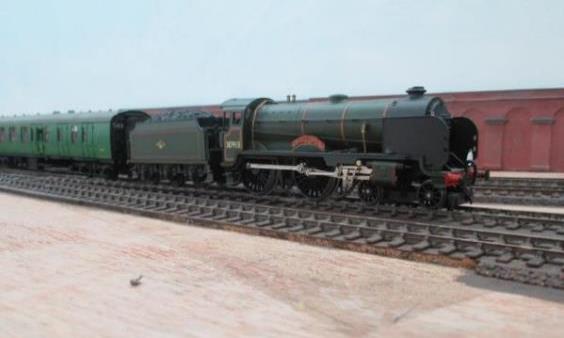
In addition, a further unit was converted to an
earlier Batch 1 /Phase 1 unit (no.6008) with its roof-mounted lighting conduits
on both coaches, 1951-type control gear and full-length running boards on the
DTC. This Batch 1 conversion created a (currently spare) 4 EPB MBSO (whilst
corrected the roof on 2H Hastings unit no.1121; that is no lighting trunking)
leaving DTS components for future conversion into a 4 EPB Trailer Second. A
second 2 HAP Phase ‘1’ /Batch ‘1’ unit (no.6015)
conversion is planned.
The choice of some 2 HAP unit numbers related to
minor items of interest in their history:
|
6008 |
Commenced service 23rd November 1957.
This Phase ‘1’ Batch ‘1’ unit was involved in a converging collision (with nos.6073
& 6015) in Gillingham depot 9th October 1962. Yellow
warning panels applied 7th January 1966. |
|
6015 |
In preparation. Commenced service 12th
March 1958. This Phase ‘1’ Batch
‘1’ unit (with no.6073) was in a
converging collision with no.6008 in Gillingham depot 9th October
1962. Date yellow warning panels applied is not known. |
|
6049 |
Commenced service 24th January 1959. Amongst the first of the Phase
‘1’ Batch ‘2’ units delivered; being stored at
Gatwick by 14th March 1959 before entering service. Yellow
warning panels applied 1st March 1965. |
|
6053 |
Commenced service 18th February 1959. Entered service on the Central
Division end-March 1959. Date yellow warning panels applied is not known. |
|
6058 |
Commenced service 28th Feb 1959. (Green)
unit in collision with loco E5003 at Ashford 19th Dec 1966. Date
yellow warning panels applied is not known. |
|
6061 |
Commenced service 8th April 1959. Units nos.6061 & 6062 involved a
sidelong collision with 4 CIG no.7345 at Wimbledon Park depot 24th
October 1984 (DTC 75379 damaged). Date yellow warning panels applied is
not known. |
|
6073 |
Commenced service 13th
June 1959. Unit (with no.6015) in converging collision with no.6008 in
Gillingham depot 9th Oct 1962. Date yellow warning panels
applied is not known. |
|
6074 |
Commenced service 27th July 1959. Fitted with Commonwealth bogies at
inner end of each car during April 1960 as a prototype for 'Phase 2' HAP
units on order thence used on high-speed test trips between Lancing and
Chichester in September 1960 (reverted to normal May 1961). Date yellow
warning panels applied is not known. |
|
6082 |
Commenced service 23rd July 1959. Unit withdrawn and motorcoach
extensively rebuilt in 1984 as a GLV for the Victoria to Gatwick service. Date
yellow warning panels applied is not known. |
|
6094 |
Commenced service 22nd Aug 1959. Unit
received Yellow warning panels whilst in green livery with no record
of subsequently being fitted with air-horns or UIC yellow 1st
class cantrail banding until it was repainted blue with full-yellow end
during a C1 overhaul at Eastleigh (outshopped 11th April 1969). A
photograph dated Sunday,
27th August 1967 on BloodandCustard shews it in this condition. |
|
6097 |
Commenced service 16th September 1959.
Built as unit
no.6098 but renumbered prior to entering service. Date yellow warning
panels applied is not known. |
|
6104 |
Commenced service 3rd October 1959.
Received side damaged
between Beckenham Junction and Shortlands from an open door on a passing boat
train 16th January 1961 (repaired at Selhurst); such incidents
used to be all-too frequent and in my railway career I’ve found (and
safely closed) several open doors whilst travelling on moving trains. Date
yellow warning panels applied is not known. |
One minor technical issue was found with the 2 HAP
(and 2 EPB units) being the use of the shorter of the two intermediate coupling
bars for when propelling on curves the roof-mounted jumper boxes could catch.
Accordingly, the longer of the two coupling bars were employed.
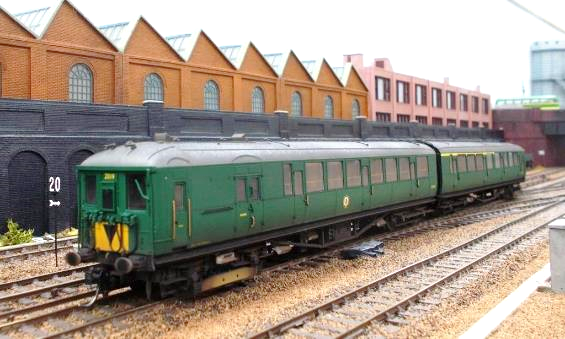
|
Solo TMC De-Luxe weathered 2
BIL unit no.2019 in its post 2nd December 1964 condition with
yellow warning panels, air-horns and yellow UIC 1st class cantrail
banding on the DTC it was withdrawn in this livery on 3rd January
1970. Stencil Headcodes were still to be fitted to the model. |
2 BIL /2 HAL
Hornby produced the excellent 2 BIL stock with a 4
COR anticipated before the 2 HAL was released; the latter being ideal for the
semi-fast trains. However, that was not to be, so there are currently 2 BIL
/2HAL units undertaking these services. Perhaps Hornby will reconsider a 4 COR
unit once they can locate their research material? - I suspect the ship may
have sailed on this.
David Rogers at Ultrascale has produced
excellent replacement driving wheels for the 2 BIL /2 HAL units as their
flanges are a little too deep for finescale track. All the motorcoach wheels
being solid (due to the unit’s electrical pickups) with only the Driving
Trailer Composite requiring standard 25.65mm pinpoint axles (as used in Hornby
coaches). The Hornby drive pinion is being fitted onto the solid-backed driven
axles. The trailing bogies of the Motorcoaches also require solid backed wheels
for the electric pickups.
For the 2 BIL Kadee no.19 couplings are used with
no.18 for the 2 HAL. Whilst this electric stock never had buckeye couplings (it
was fitted with screw-couplings), these are used on the model purely out of
operational convenience.
|
2019 |
Little of note apart from wartime damage at Brighton
(18th May 1942) and collision damage (February 1951 back to
traffic 8th May 1951). Model in its post 2nd December 1964
condition with Yellow warning panels. |
|
2090 |
MBS 10656 damaged in Eastbourne
sidings when struck by unit no.2947 10th January 1965, to
Micheldever for store until moved to Eastleigh for repair 27th
July 1965 and released 27th August 1965. |
|
2132 |
MBS 10698 damaged in
side-scrape with unit no.2148 at Farnham 22nd June 1964 and to
Wimbledon Park for repairs. |
|
2142 |
Sadly, little of note to report until it received
yellow warning panels in 1964 (not modelled). |
|
2611 Hybrid |
Unit in collision with 2 BIL
2113 at Wimbledon Park about Sep-59 and DTC 12196 damaged and exchanged with
12146 (ex.2113) from 14th September 1959. Unit ran in service
whilst 12196 repaired, unit ran mis formed until sent to Lancing for overhaul
14th November 1960 and reverted to original formation when
released 16th March 1961. Diagram no. of DTC 12196 amended to
2702 during the above overhaul at Lancing. |
|
2630 |
Diagram no. of DTC 12215
amended to 2702 during A1 overhaul at Lancing between 25th
February 1959 and 4th May 1959. Date of UIC First class yellow
band is unknown. This unit received its Yellow warning panels 21st
July 1967. However, the decision was made to accept this model rather than
renumber it just to have an earlier 2 HAL with yellow panel from 13th
December 1963-on. |
|
2639 |
Diagram no. of DTC 12224
amended to 2702 during E5 overhaul at Lancing between 27th
September 1960 and 4th January 1961. Date of UIC First class
yellow band is unknown. This unit received its Yellow warning panels 2nd
July 1965. However, once again the decision was made to accept this model as
is. |
Ajay all-steel 2 HAL
units will also feature having strayed on the Gatwick services /West Coastway. Such straying was not improbable for in later
years the occasional 4 VEG Gatwick unit appeared at Hampton Court when the 4
VEP /4VEG formation became reversed, so the 4 VEG picked up an afternoon
diagram down to Horsham, up to Waterloo thence out to Hampton Court before
returning the same way!

|
5 BEL unit 3053 before it was backdated by
removal of its yellow warning panels and its couplers replaced. |
5 BEL
Two of Hornby’s 5 BEL units are in store
ready to use following the replacement of the yellow warning panel with a
pre-1959 style Pullman crest on no.3053 (unit no.3053 never carried the later
style of crest). Only the fitment of end-couplers on both is required to enable
ten-car operation; probably placing the powered bogies back-to-back in the
process.
The first batches of Hornby’s Brighton Belle
used intermediate couplers with electrical connections between cars; later
models having simple tension-lock with pick-ups on each bogie for the lighting
on each car. As close-coupling was being sought the earlier vehicle underframes
using couplers with electrical connections were not needed.
So, the running gear /underframes of one unit
(no.3052) was swapped over with a third spare no.3053 so both coupled units can
use proprietary close-couplers throughout rather than Hornby’s DCC
power-coupling . The third spare unit went to friend who wanted no.3053 with
a power-coupling for his DCC layout. All that is needed now is an excuse to
run a 10 BEL through Ewhurst Green.
David Rogers at Ultrascale has produced
excellent replacement driving wheels for the 5 BEL units as their flanges are a
little too deep for finescale track; all the motorcoach wheels being solid (due
to the unit’s electrical pickups) with only the Trailer Cars requiring
pinpoint axles. The Hornby drive gear is being fitted onto the driven axles.
In terms of these Pullman (umber & cream)
liveried 5 BEL units it was discovered that the unlined area beneath the driver
and secondman’s forward observation lights down to the buffer-beams and
behind the jumper cables /sockets is unpainted, being the colour of the plastic
bodyshell. This is somewhat darker that the painted sides, but until examined
isn’t immediately noticeable. However, once noticed it does rather stand
out so my advice is don’t look too closely at the front of your umber
& cream 5 BEL units!
|
3052 |
Received its late crest during August 1961
with whistles (modelled) replaced with air-horns outshopped Eastleigh 20th
March 1964. Outshopped yellow warning panels 20th
April 1966. |
|
3053 |
Post-1958 car letter /numbering style with early
crest with air-horns (modelled) replacing whistles by March 1964. Outshopped yellow warning panels 6th
January 1967. |
Without
further alteration, this could date the pair of 5 BEL units running together to
March 1964. It was always hoped Hornby would have produced a pair of 1950s 5
BEL units, but this now appears unlikely and there are so many other priorities
ahead of further backdating these units.
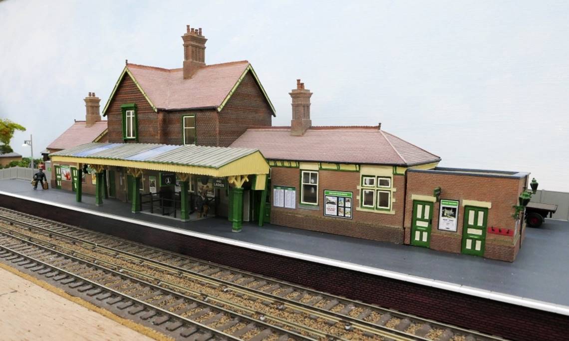
|
In early BR Green
livery, 3 Car Motor Unit (now augmented to 4 SUB no.4428) on the Down Line.
With a view towards development potential, Ewhurst Green could have been the
furthest extent of the 1925 electrification (eventually extended through to
Havant). |
Suburban Electric Multiple Units
2 NOL /4 SUB /4DD
Suburban services use 2 NOL stock (no.1883) and a
pair of augmented 4 SUB units (nos.4424 & 4428) in early Southern Region
multiple-unit green (with unicycling Lion totems). A number 4 SUB Sheba and
Mary kits are ready for construction having been let down by two kit builders.
|
1883 |
Unit converted July 1936; withdrawn 14th December 1957 (with underframes used in the construction of SR-type 2 EPB units). |
|
4424 |
3-car
Motor Unit augmented to 4 SUB 4th February 1947; withdrawn 7th
April 1956. Steel trailer converted to EP braking for 4 EPB unit 5232 in
August 1956 (with remaining underframes used in the construction of SR-type 4
EPB units). |
|
4428 |
3-car Motor Unit augmented to 4 SUB May 1947; withdrawn 14th
April 1956. Steel trailer converted to EP braking for 4 EPB unit 5230 in
August 1956 (with remaining underframes used in the
construction of SR-type 4 EPB units). |
|
4001 |
BR(S) Green 6th
February 1958 to 23rd April 1965. Delivery awaited. |
|
4002 |
BR(S) Green 14th
February 1958 to 18th June 1965. Delivery awaited. |
Following KR Models October 2021 announcement of
ready-to-run 4DD units, a pair were immediately ordered as these units used to
pass down the Mid-Sussex line en-route to Fratton
(thence loco-hauled to Eastleigh Works). Else could they have been redeployed
(in a short trial to relieve overcrowding) on a peak-hour service into Holborn
Viaduct where electric trains were limited to eight-cars?
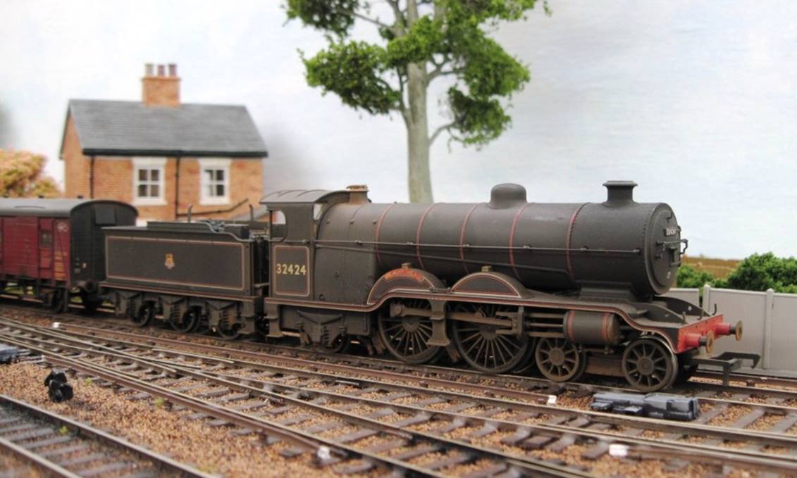
|
2 EPB no.5734 in the
autumn sunshine. I cannot recall why this unit number was selected for it led
a stoically uneventful career on the Southern Region. |
2 EPB /4 EPB
Bachmann’s 2 EPB is excellent and besides
these BR-type two-car units some conversions to create BR-type 4 EPB units
(Bachmann) are in-hand. In addition, No-Nonsense SR-type 2 EPB & 4 EPB
units are awaiting kit-building. Currently 2 EPB units nos.5708, 5715, 5734,
5759, 5770 and 5771 are in service. Now preserved, unit no.5759 was
commissioned by Lord & Butler (Cardiff) and featured yellow warning panels, its headcode 2 denoting
the West Croydon - Wimbledon service upon which the unit first operated upon
entering service in 1956.
Most of these 2 EPB units led uneventful lives:
|
5706 |
Commenced service 30th April 1956 as
modelled before receiving yellow warning panels 2nd October 1964. Unit failed at
Bingham Road 28th October 1961 then damaged in collision with
no.5746 which had been sent to assist. It was repaired at Slade Green. |
|
5715 |
Commenced service 1st September 1954 as-modelled before receiving a yellow warning panel 27th
April 1964. Unit damaged in shunting collision at Addiscombe depot 22nd
December 1961. Whilst no.5715
was against the stops in no.2 siding (10-car as coupled to no.5038 thence
no.5149) a 6-car train (no.5758 + 5102 forming 10 45pm ex. Hayes) ran into
the 10-car train’s rear leading to minor damage (including couplers) on
all units. |
|
5734 |
Commenced service 4th June 1955
as-modelled before receiving yellow warning panels 1st July 1964. |
|
5759 |
Commenced service 20th June 1956 but
the application date of its Yellow warning panels (as modelled) has
yet to be determined (early 1964-on). |
|
5770 |
Commenced service 5th September 1956
its condition at least to 1964 (the date of its yellow warning panels has yet
to be determined). |
|
5771 |
Commenced service 17th September 1956
its condition at least to 1964 (the date of its yellow warning panels has yet
to be determined). This unit starred in an episode of ‘The Edgar
Wallace Mystery Theatre’ (‘Accidental Death’
released November 1963) having been filmed at a renamed Merton Park station. |
One minor technical issue was found with the
Bachmann 2 EPB (and 2 HAP units) being the intermediate coupling bar, for when
propelling on the storage loop’s 36” curves compression between
cars meant the roof-mounted jumper boxes could occasionally catch. Accordingly,
the longer of the two coupling bars supplied with the 2 HAP unit were employed;
Bachmann spares department conforming these were the same as those used in
their TOPS class 101 diesel mechanical units (part no.36-066). Such parts are
usually obtained from Peter’s Spares.

|
Motor Luggage Van 68006 draws an arc on the Up
Line. |
Conductor Rail Arcing
Ewhurst Green is fitted with an arc-flash device
tucked in behind a conductor rail off-ramp. Arcing typically (but not always)
occurs at conductor rail off-ramps, frequently in and around junctions.
The model’s arc-flash is emitted from a tiny
but bright LED barely visible tucked in the ballast alongside the conductor
rail on the same-side as the adjacent running-rail. The arc-flash LED is
operated by a reed switch (in the four-foot) which is triggered by passing
neodymium magnets fitted under the trailing bogie of some units.
Both the reed switch and the magnet are offset
(magnet is on the secondman’s side) so the reed switch will not be
triggered by a magnet placed under a leading bogie from (say) a turned unit.
At an early stage it was decided not to equip
(powered) motor bogies of the model electric units with these powerful
neodymium magnets.
Magnets on Electric Units
A 10mm by 5mm by 2mm magnet is used on 2 BIL /2 EPB
units glued on-edge to the inside of the bogie between the axle boxes (hidden
behind the shoe beam) while 2 HAL units needed a 10mm by 3mm by 2mm magnet.
Similarly (and because of the bogie design), the 4 CEP /2 HAP /MLV models
require a longer 15mm by 5mm by 2mm magnet. As an aside and in terms of the
glue, a small amount of Pritt Stick is used on all but the 2 HAL units which
require the greater strength of Superglue!
Uni-directional Arc-flash Device
At one location the arc-flash device will be
located at the ramp-end of a floater; this will be traversed by suburban
electric trains terminating at Ewhurst Green (before returning to London) so
will be crossed by the same train in both directions. It is assumed that the
driver had to apply power before coasting into the platform.
‘Floaters’ are short sections of
conductor rail normally found in areas of S&C (i.e. switches and
crossings).
In order to ensure the arc-flash device will only
operate for Down trains (entering Platform 1 but not leaving) the device will
be fed from the (smoothed) 12v DC feed to the Down to Up Loop turnout motors on
the facing crossover from the Down line. This means the LED will only
positive-energised with the crossover reversed (for moves from the Down to Up
Loop. Although the arc-flash device comprises an LED, a second, larger diode
will be used to protect the arc-flash device when the turnout motor feed is (normally)
reversed (i.e. negative-energised).
Chapter Twenty-Eight
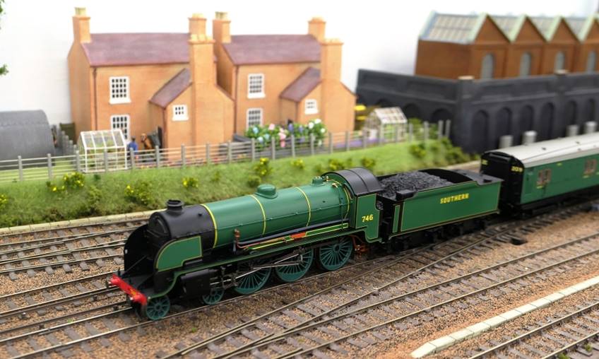
|
00 works L1 number 31778 hauling an unfitted
freight around the test circuit; this being taken prior to laying any of the
scenic main line track. |
28. Rolling Stock (Locomotives)
Motive Power (Steam)
Bachmann’s E4, C, Standard 4MT bacon-slicers
and Fairburn tank classes are excellent as are Hornby’s Q1, Black Motors,
A1x, H and M7 tanks and OO Works H-tanks and Black Motors. The only BR numbered
K10 with Southern on the tender was also purchased from OO Works (instead of
the incorrect British Railways or BR emblem produced by OO Works to fulfil the
demand by many); this being the only model in this livery to come off
Roderick’s production line (post-production an SR-numbered
model was subsequently altered by OO Works to give a BR number for a customer).
In terms of mainline locomotives Hornby’s WC
/BoB /MN (all now made in air-smoothed and rebuilt
forms) are also superb along with their V and S15 /N15 variants. Even a LN
appears on a (very rare) diversion to Southampton during engineering works at
Woking. By this time the N15x class were established on the Basingstoke
services although occasionally one would appear on the Southampton Fareham
Waterloo peak-hour services. OO Works L, Black Motors, N15 & H15 classes
feature with Roderick’s D15 running off its normal Brighton Southampton
routing. There is even a much-modified Triang L1!
Recently Bachmann’s Marsh H2 Atlantic
no.32426 St Albans Head was renumbered & renamed (plus weathered) by TMC. St Alban’s
Head is located just along the coast from Swanage in Dorset hand (unlike the
other H2 names) has a Coastguard Station instead of a Lighthouse. Built in
January 1912, no.32426 was withdrawn in August 1956.
As Ewhurst Green provided an alternative South
Western route to Havant (and beyond) South Western Division (SWD) locomotives
with their bogie tenders would be regularly seen passing through Ewhurst Green.
On the Central Division (CED) locomotives (such as the N15) were paired with
six-wheeled tenders; by virtue of the shorter distances covered, they did not
need the larger capacity tenders and the increased unnecessary weight that came
with these. No doubt the build /ongoing maintenance cost of tenders had also
been factored by the commercially-aware Southern Railway.
Some suggest turntable size was the reason although
this may not necessarily the case for the wheelbase of a bogie tender was only
around seven-feet longer. Indeed, a number of CED turntables that could not
accommodate (say) a S15 with a six-wheel tender (such as New Cross Gate
49’ 9” and St. Leonards West Marina 49’ 11”). However,
a significant number of CED turntables were 59’ 9” (Three Bridges)
or 59’ 10” (Brighton, Eastbourne, Newhaven). Victoria (Central) was
60’ 0” and Redhill was 64’ 10”.
Notwithstanding this, two S15 locomotives are ready
to be paired with six-wheel tenders, these being Brighton-allocated no.30835
with an ex-N15 tender (no.30847 was similarly paired) and Redhill-allocated
no.30837 with an ex-Schools tender (both tenders were not lined and had late
crests with left-facing lions).
The layout doesn’t stop with extra-detailed
ready-to-run; for example, South Eastern Finecast
make excellent kits of the D, E5, Q & P classes and they supply the ideal
chassis to go under the Golden Arrow Productions E1-class (in my opinion this
having the potential to be more accurate than the elderly DJH kit).
Shunting and short-length train movements down the
lightly-laid branch into Dunsfold Aerodrome are (at various times) undertaken
by A1x, P, and B4 tank engines before USA tanks were released from Southampton
(one of these was allocated to Guildford).
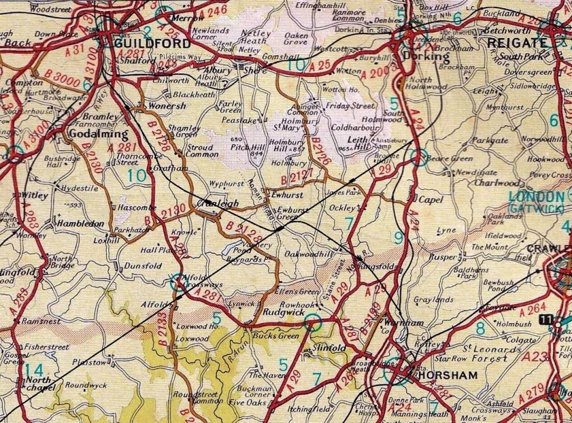
|
Appropriately weathered Heljan
no.D6580. Strictly speaking this model shouldn’t be produced equipped with
Buckeye couplers and compression bars (now since removed). |
Motive Power (Diesel)
Following the arrival of the Sulzer type 2 (class
24) locomotives on loan from the LMR, Southern Region type KA Crompton diesel
engines (class 33) start to appear with a KA-1A no.D6587 (TOPS class 33/2 aka
Slim Jim repainted into plain green) and the pull-push D6580 (forerunner of the
TOPS class 33/1) although this unique locomotive (trialled on the Central
Division) is pushing the boundary of my modelling period.
Kernow released their models of 10201, 10202 and
10203 although slightly before my time-period. As each were very similar a
compromise was reached with Brighton-built 10203 releasing a BR peak (TOPS
class 46) to find a career in the Algarve!
Heljan produced a model of North British Locomotive
number 10800 in its BR Early Emblem Black /Silver bogies post-February 1954
condition (with the lower bonnet door vents). As a prototype diesel locomotive,
it was underpowered and troubled by reliability issues so spent much of 1954 in
works. It was moved from the Southern on 11th December 1954 and
allocated to Plaistow shed on the Eastern Region before withdrawal in August
1959. With the factory weathering poor, one of these was only acquired after
these were placed on offer by Rails of Sheffield.
Having bought a Silver Fox version many years ago
(D2997), Heljan’s TOPS class 07 is a nice
model, but an initial decision was made not to purchase one of these 1962-built
locomotives. However, temptation succumbed, and another example of the class
(D2988) can now appear alongside a few other BR(S) diesel shunters.
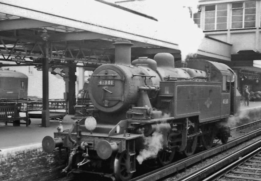
|
EFE Booster locomotive no.20002. Nicknamed ‘Hornbys’ no.20002
leads some Bachmann coaches |
Motive Power (Electric)
Southern Railway
Courtesy of EFE, Bulleid /Raworth Co-Co electrics
no.20002 appears on the layout sporting (at different times) BR black and BR
green livery. In respect of Ewhurst Green’s period, there is 20001
(Green), 20002 (Black) and 20002 (Green) - these were originally numbered by
the Southern Railway as CC1 and CC2.
These locomotives (along with the later type-HA)
had an internal booster unit - essentially a electric motor-generator unit
(with a intermediate flywheel in CC1 /CC2 & CC3) which reduced the surging
associated with conductor rail gapping. These booster units were not powerful
enough to move a solo locomotive any meaningful distance. However, could
provide a significant power boost to the locomotive during haulage.
Overhead Contact Wire
With a view to expanding its electrification
through the use of electric locomotives on freight and in order to enable
electric locomotives to collect /drop-off trains within freight yards, the
Southern Railway considered the use of low-speed overhead to be cheaper than
the installation /operation of conductor rails. By implication safer, overhead
contact wires would also eliminate the potential gapping problems; particularly
those associated slow movements on conductor rails within depots and yards.
Accordingly, in 1941 the Southern Railway installed
lightweight overhead wiring at Brighton and Balcombe yard for testing its new
electric locomotives numbered CC1 and CC2 (later followed by CC3). This
comprised a simple ‘tramway style’ overhead contact wire (without
the need for catenary wires) and was pressured at line voltage (nominally
650-750v DC) with locomotives restricted to 15mph.
Under British Railways’ Kent Coast
electrification, lightweight overhead wiring was subsequently installed at
Angerstein Wharf, Betteshanger Colliery, Bricklayers Arms, Deal, Dover Town,
Faversham, Hither Green Goods, Hoo Junction, Maidstone West, Plumstead, Shepherdswell, Sittingbourne, and Snowdown Colliery.
Drivers exiting Hither Green Goods had to swiftly lower their pantograph before
a colour light bracket signal removed it!
Whilst it would be interesting to model the
overhead contact wire this could be overkill and the transitioning between
conductor rail /overhead would be difficult to achieve with any realism as the
overhead wire would need to start above passenger running lines.
British Railways
Besides the Southern Railway’s Bulleid
/Raworth Booster locomotives, it has been assumed that British Railways’
1958-built type-HA (later TOPS class 71) electric locomotives also ventured on
this route working freight across to /from the South Eastern Division via
Factory Junction and Pouparts Junction; certainly,
they worked on the other divisions.
On the Central Division this included hauling the
Newhaven boat trains with a steam locomotive inserted to ostensibly provide
steam heating (although double-heading did on occasions, unofficially occur)
and had been seen on the West Coast through Chichester. On the South Western
the 90mph type-HA locomotives often travelled to Eastleigh Works; sometimes
with burst armatures from excessive speed (the figure of 115mph having been
bandied about internally within the Southern Region).
Hornby’s plain green front with red-stripe
version of the type-HA number E5022 in as built (without cantrail rain strips)
also features on freight traffic across from the SED. To-date this appears to
be the only current HA model produced in pre-September 1963 guise (i.e. without
cantrail rain strips). Weathering of these will be interesting as they were
kept relatively clean albeit getting shabby approaching withdrawal (in BR blue
livery).
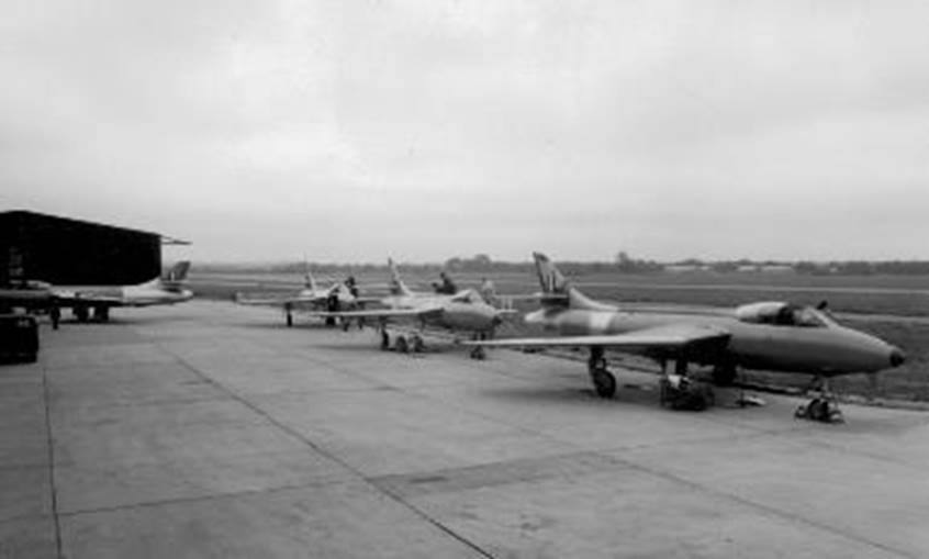
|
At one stage NBL Type 1 locomotives (in this
instance no.D8400) visited the Southern (often via the East London Line);
usually on freight workings but sometimes hauling passenger excursion trains. |
Strangers on the Southern
There is always the temptation to have a huge
number of one-offs and visiting locomotives; an area where I am actively
seeking to prune back past purchases. For example, a Black 5, two 8Fs and WD
were reduced to a type 1 NBLs (later ‘TOPS’ class 16) which ran
through to the Southern Region (including
at least one passenger excursion into Brighton). Equally there was no
additional need for the not dissimilar EE type ‘1’ (later
‘TOPS’ class 20) and BTH type ‘1’ (‘TOPS’
class 15) which were intended for Apothecary Street; these having been sold on
as unused .
One type of locomotive upon which more research is
required are the Baby Deltics which occasionally ran onto the Southern although
were too heavy for use through Snow Hill. A retired driver and friend (sadly
now passed) remembered working on one (as a secondman)
into Hither Green via the East London Line.
The East London Line was a useful connection from
the Great Eastern onto the Southern lines although its gradients the lowest
point being Wapping) were a limiting factor, as was the necessity to reverse in
Liverpool Street station. These trains were usually headed by J69
(‘Buckjumpers’) 0-6-0T locomotives (often in pairs) thence BTH and
NBL Type ‘1’ Bo-Bo diesel locomotives (these becoming class 15 and
16 under TOPS) until the freight traffic ceased in 1966. Of interest on the line,
up to 1955 a hoist was used for conveying wagons between Shoreditch station and
Bishopsgate Goods Depot.
Even the Fell diesel 10100 and DP1 ventured onto SR
metals albeit both loco-hauled to Eastbourne (Fell - 1951) and Battersea (DP1 -
1957) respectively. However, with one exception I’m not venturing to such
rarities as I believe a layout needs to concentrate on the regular (if mundane)
everyday stock and operations!
There are records shewing a Metro-Vick Co-Bo
(D5714) working through to Norwood Yard thence down to Three Bridges in April
1960: this rare visitor to the Southern being the exception simply too
interesting to resist on the layout. The model is weathered and equipped with
Ultrascale wheels.
Chapter Twenty-Nine

|
00 works L1 number 31778 hauling an unfitted
freight around the test circuit; this being taken prior to laying any of the
scenic main line track. |
29. Rolling Stock (Freight)
Freight Stock
Ewhurst Green has a large selection of freight
stock available, and I shall not bother to blether on about wagons most of us
are well-aware off. However, there are a few items of interest.
Parcels and Mail Traffic
The level of mail carried by the
railways can be easily forgotten and this is not always well represented in
model railway form; possibly because much of the traffic took place overnight.
Fortunately a plethora of vans are available (including other regions coming
onto the Southern) and great advantage was taken of these. Besides the hauled
vans Ewhurst Green also has several Motor Luggage Vans which on occasion hauled
vans as well as being in electric train formations.
Bananas by Rail
Pre-war, the large bunches (on the stem) of unripe
Bananas were conveyed in crates and were most likely to be varieties such as
the thicker-skinned Groa Michel. During the fifties Fusarium oxysporum (an ascomycete fungus) devastated banana plants
with many varieties becoming commercially extinct. By the sixties the resistant
Cavendish banana had been developed (named after 7th Duke of Devonshire William
Cavendish) and these 'hotel bananas' have since dominated the trade.
During the
thirties Bananas were imported through Southampton Docks and the Southern
Railway built a fleet of steam heated vans. The Southern also hired vans from
the LNER; most with SR branding on their sides.
Just after the
Second World War, Geest bananas opened its ripening
sheds adjacent to Lingfield station, these being served by daily train of up to
some thirty vans (arriving as the 5.15am from Norwood Down Yard).
Towards the end of the nineteen-fifties, the
importation of Bananas changed with the large, crated bunches being replaced by
ready-trimmed Bananas packed into cardboard boxes. Accordingly, the quantities
carried were increased and the handling of bunches in wooden crates eliminated.
When Accurascale released
its SR steam-heated banana vans a weathered train was obtained from The Model Centre. With the advent of cardboard boxed Bananas, some of these
SR banana vans had their steam heating removed in favour of a through
steam-heating pipe (denoted by a yellow spot on the van’s side). Mixed
amongst these SR banana vans are a couple of Oxford Rail Eastern
Region (ex.LNER) as these still work onto the
Southern.
Albeit now a dated model, the yellow-spot Dapol Banana van-train
(prepared several decades ag) still looks good passing through Ewhurst Green
– presumably en-route to /from Norwood Yard
thence Geest’s ripening sheds at Lingfield.
With their corrugated ends and plywood sites, these Dapol
Banana vans appear to be of the Lot 3209 built at Wolverton 1959. All are
bauxite being unable to locate a BR prototype for the much-modelled yellow
Banana van (a van or two may have been painted yellow in the thirties as a
promotional livery). In addition to weathering, these wagons have been fitted
with scale wheels.
Whilst
these 1959-built Banana vans were constructed with improved insulation, they
were not equipped with steam heating apparatus. However, as they needed to work
with older steam-heated Banana vans they were fitted with through steam-pipes
and the Yellow Spot denoted this.
However,
in 1963 these steam-pipes ceased to be used and were steadily removed as vans
underwent maintenance. The last commercial movements of Banana vans on the National Rail
Network was in 1979.
Powder Traffic
The Delabole Slate Company
Ltd
of Delabole had some four dedicated Presflo's for the conveyance of slate powder (under the
brand name Delafila) along with an as well as an
unknown number of Covhops. These Presflo
wagons were procured from ICI’s salt division having been built by Metro-Cammell (to Lot 3029) in 1957 and (according to Kernow’s
release) Gloucester Railway Carriage & Wagon Works in 1961. Kernow Model Centre
commissioned a Bachmann three-pack (cat. no.38-260Y) of these ‘Delafila’ wagons (Covhops
also featured in Bachmann’s range) with TMC undertaking their weathering.
Presflo wagons were
also used for the carriage of cement and some weathered ‘Blue
Circle’ versions also make the occasional appearance.
Volkswagens by rail
Many decades ago a trainload of T1 & T2
Volkswagens was prepared for Apothecary Street; the T1 being Type 1 (i.e. VW
Beetle car) and T2 being Type 2 (i.e. VW microbus /samba, van & pickup).
Albeit at 1:72 scale, these Cararama models appeared
long before today’s plethora of ready-to-run 1:72 vehicles.
In Ewhurst Green’s era (indeed up to 1967)
the T2 buses were split-screen versions before the modernised bay-window
appeared. I owned and enjoyed a T2 split-screen camper complete with
Canterbury-Pitt pop-top .
There are sufficient VW-loaded wagons to form two
18-wagon trains (else one very long one) at exhibitions see if the eagled-eyed
could spot there were actually two trains (only one contained a red T1 Beetle
car) else as one impressive forty-wagon train.
A 1963 beetle no.53 Herbie was also acquired lest
this appealed to younger exhibition audiences; this being from the 1968 film
The Love Bug (which was based on the 1961 novel Car, Boy, Girl by Gordon Buford).
Isetta Bubble Cars from Brighton
Oxford Diecast brought out a lovely model of the Brighton-built BMW Isetta which were built between 1957 & 1962 at the former locomotive
works, being shipped out by rail three to a Lowfit wagon; an early batch being
exported to Canada. Both right and left-hand drive four-wheeled versions were
made at Brighton, with the UK’s three-wheeled version being introduced in
1959 following the decision that even with its closely spaced rear wheels
(around 18”) the four-wheeled Isetta could not be driven on a motorcycle
licence. Unlike the standard bubble window design, these ‘export designs’
of car had sliding windows.
Using the Oxford Diecast Isetta cars a model
train is already in preparation with the weathered Lowfit wagons awaiting their
cars. Although Red /Yellow Isetta cars have been purchased, a third
prototypical colour is sought so every loaded combination of three coloured
cars could be modelled yielding 27-wagons in total!
Oxford Diecast produced the RAC Isetta (just six of
these were used in London) and a pink coloured Isetta although this was sadly
not a factory colour.
Cararama had previously made 1:72 models of the BMW (Bayerische
Motorenwerke) Isetta. However, these came with open sunshine roof (which doubled as
an escape hatch in the event of a collision) and with a luggage rack (wicker
basket atop) were not suitable for placement on a leaving-the-factory train
without much work to alter them.
Chevrolet Trucks
Many years ago Cararama
produced some rather nice 1950 Chevrolet trucks - American-built vehicles being
far more commonplace in the UK just after the war than in (say) the late-fifties.
A short trainload of six of these trucks on Lowmac
wagons was prepared over thirty years ago and it still makes occasional
appearances today.
Plate & Bolster Wagons
The Model Centre produce
plate and bolster wagons; their weathering is superb. Some have been fitted
with TMC’s realistic plate loads.
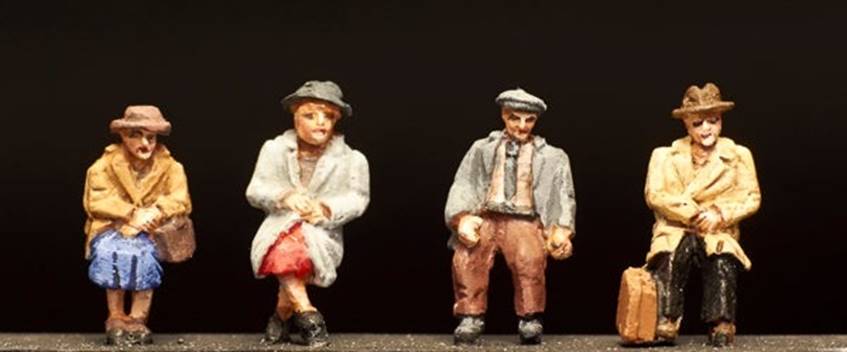
|
Two chemical
tanker wagons as weathered by TMC. Sheffield
Chemical Co. Ltd (Attercliffe) |
Tanker Wagons
Ronuk of Portslade
Ewhurst Green took taken delivery of the two Ronuk tanker wagons (these served the Ronuk
Ltd factory at Portslade which produced polish); Bachmann models superbly weathered by The Model Centre (from a
rare colour photograph) to include the acid-wash staining on the tanks.
Petroleum and Oil
A number of different Berry Wiggins oil and
petroleum tankers were also sent to TMC for weathering, once again the results
were superb; these operated out of Hoo Junction (and other locations). Esso
(including Power) and Shell tank wagons were also prevalent on
the Southern and some of these are now appearing.
Chemicals
Few can forget Mainline’s
delightful Crossfield Chemical’s tank wagon no.49 and in 2010 model shop
Waltons of Altrincham produced a weathered three pack of green-livered Crossfield
Chemicals Ltd (Warrington) tanks; these being subsequently augmented with a
further weathered tank in green and in Crossfield’s later blue livery.
Having visited the shop many times over past
decades while working in Manchester, sadly Waltons closed (retirement) on Saturday 15th March
2025.
There is an interesting book on Joseph Crosfield
including his business links as a shareholder with the railway industry.
TMC also weathered some chemical tankers such as Paper
Makers Chemicals Ltd (Kent), Sheffield Chemical Co. Ltd
(Attercliffe), Lindsey & Ketseven Chemicals
Ltd (Saxilby) and Rothervale
(Rother Vale Collieries Limited of Thurscroft).
Engineering Stock
Rapido produced the ex.
SECR 6-wheeled brake van in BR Engineer’s Black which was a welcomed
addition along with its BR grey versions.
EFE’s excellent LSWR Cross-Country set
provided an opportunity to create green-liveried 2 LAV set 312 with the spare BTL from this set renumbered
as DS1905 (Redhill).
Kernow released an ex. LSWR road van DS 54538
‘Return to Three Bridges’.
Whilst Bachmann’s superb Wickhams inspection
trolley might appeal, these only normally ran during engineering possessions,
so I’ve passed on one of these otherwise delightful models.
Breakdown Trains
Bachmann’s superb Ransomes & Rapier 45-ton steam crane could not be ignored; particularly as Guildford
shed’s crane was modelled in SR-grey; a livery it carried into the
fifties.
A ‘Pilchard’ has been suitably
weathered for possible use in a breakdown train.
Engineering Trains
Engineer’s wagons (mainly Grampus, Mermaids,
Whales and a few Dogfish) will also be seen overnight at Ewhurst Green.
In terms of
wagons, Rapido produced ex.SECR ballast wagons, Dapol the
Grampus ballast wagon and Lima Sea-Cow bogie-ballast wagons were converted to
SR vacuum-fitted Walrus. Heljan produced a Dogfish
model and Hornby a Trout.
Flangeway produced a superb model of a Mermaid
side-tipping ballast wagon. Although these weren’t particularly common on
the Southern they were used and a trainload is in preparation. The side-tipping
design of the Mermaid was inherently dangerous leading to a number of serious
and life-changing incidents with staff.
Cambridge
Custom Transfers produce an
excellent range for these and other wagons.
Chapter Thirty
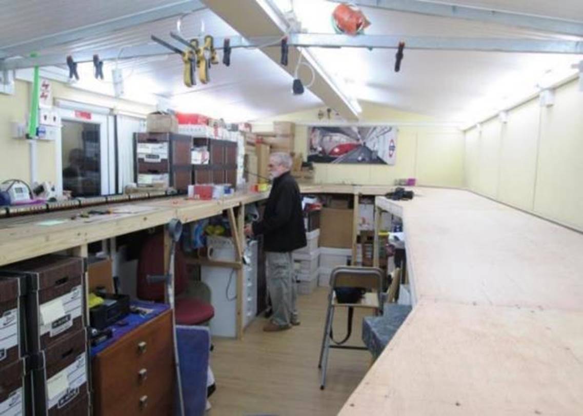
|
BR Standard No.71000 Duke of Gloucester hauling
eighteen bogies! A permanent blue-brick retaining wall in
engineering blue-brick has now been fitted at this location; Somersbury Lane bridge is complete and both a modest
single-story northlight works, and adjacent offices now stand atop the retaining wall behind the steam locomotive. |
Interestingly most of the trains that have operated on my layout’s test-tract belong to fellow East Sussex Finescale members and the current record for the slowest lap currently stands at eighteen minutes eight seconds with a visiting pre-First World War Prussian 0-8-0! (This was using an elderly but serviceable H&M controller and could be significantly improved with modern controller sophistication). When time permits, this may be attempted with a Model Rail (Bachmann) USA tank.
In terms of train length this is currently held by
Terry’s ( the Rigger ) no.71000 Duke of Gloucester hauling eighteen
bogies unassisted comprising eleven Mk1 coaches and seven Mk1 Metro-Cammell Pullman cars.
There are no fastest train lap records.
Chapter Thirty-One

|
Early-on, spare turnouts were loosely laid out to
assess their desired position for the station’s north-end sidings. |
31. Layout Construction Progress
2014
Layout planning commenced late in 2014 starting
with the design of the layout and its room. Much though was put into what was
wanted (in terms of a layout) and how this may be achieved. Such planning
included what part of the Southern Region did I wish to portray and the type of
models that I’d seek to run.
2015
Track laying is now well under way having been
designed using AutoCAD . The track is lightly glued /held in place by pins
before painting in Railmatch acrylic sleeper grime
and ballasting in the four-foot to keep it firmly in place.
2016
Both the London and Country-end S&C connections
into the Up and Down Main Platforms (2 & 3), Up Platform Loop (1) & Up
Loop along are laid, motored and ballasted. The Up and Down Main platform
roads, Up Platform Loop and Up Loop are all laid; the Up and Down Main lines
meeting in the middle by means of a large radius curve (this being achieved in
August 2016). The current stage is laying the Country-end carriage sidings and
freight reception sidings; these being on curves to avoid the visually
unappealing rows of linear tracks.
The Up and Down (fiddle yard) main lines were
completed in 2016 (equipped with droppers and turnout motors) but it
wasn’t until the end of 2017 /start of 2018 when the (fiddle yard) branch
lines were installed along with a Fleischmann turntable; this being used
strictly on the basis of reliability and functionality in a non-scenic setting.
2017
A decision in the Country End’s scenery meant
a realignment of the Down Branch replacing a large radius curved (trailing)
turnout with a straight leg to send the branch under Somersbury
Lane bridge rather than a sharp curve backed by a retaining wall; visually this
would be a great improvement. Marcway kindly supplied
a 48” turnout without the leg-end rails trimmed enabling a relatively
straightforward replacement /realignment.
On the main line all of the turnout motors are in
place and the track wired (I always electrically switch the common crossings of
turnouts) with the Up Main currently utilised as the test circuit. The test
circuit’s track was lifted and stored for later use for the branch
section of the fiddle yard.
With the disconnection of the test circuit the Down
Main was connected into the fiddle yard August 2017; at the same time a section
of the Up Main was re-laid (to remove a twist fault) and a trailing crossover
added at the start of the fiddle yard’s fan (enabling unscheduled stock
reversals and improved storage whilst in use as a test circuit).
2018
Completing the fiddle yard track enabled a start to
be made on the scenic boards at either end of the layout. So, plenty of tea,
biscuits and Cornflakes were purchased in order to lure Terry back from the
Algarve to undertake the work Easter 2018. This also included fabricating the
scenic curved boards behind which the railway disappears (see trompe l’oeil).
However, track-laying is relatively quick compared
to the under-board wiring which takes time, let alone the relay-operated
control system that makes everything work!
In order to provide a break from wiring some
scenery work was also started.
2019
Wiring, wiring and more wiring sadly interrupted by
a family bereavement.
The layout’s wiring is undertaken in set
cable runs secured via eyelets /cable ties to the underside of the boards.
Cables are terminated at one end and connected at the other for testing. After
testing, the cables undertake gentle pulling to remove unnecessary slack and
give a tidy appearance. The wiring is then retested.
Associated with this was completion of the control
panel for the Up and Down Main and Up and Down Branch storage loops. This
enabled the Up and Down Main storage loops to be commissioned with function
section isolators; albeit as sidings accessed from the London end. At the same
time the trailing crossover was also brought into use.
The daylight simulation fluorescent lighting was
also replaced with daylight simulation LED tubes. Giving a better output and
halving the lighting power consumption, the need for electronic ballasts is
eradicated. Whilst normally reliable, if a ballast failed its replacement could
be difficult being located above scenery. The top of the scenic boards already
included a sturdy lip upon which a crawl /protection board could be placed
above the layout. However, with a robust economic case for using LED tubes the
change was made.
2020
Wiring, wiring and more wiring was scheduled!
Unfortunately, a deterioration in my vision has
caused many problems. However, a friend Ian Sneyd has repainting the Bachmann
station building for me into Southern Region colours including fitting of extra
detail such as lozenge station signs from Trackside Signs mounted on brass backplates and cast running-in boards from Dart Castings (MJT).
2021
With help from friends the layout is progressing
with much scenery towards the south (junction end) of the station having been
undertaken. Friend has been steadily laying conductor rail. This has
necessitated finish off the ballasting at the London-end curve along with
designing the gated Horsham Lane level crossing; the construction of which is
well under way including the two houses on opposite sides on the lane
immediately beyond the level crossing.
The Down Bay platform tracks have been laid with a
view to construction of the platforms. All this is giving a much-needed boost
of enthusiasm!
Somersbury Lane overbridge is complete and the trackside
scenery up to the double-slips and the Up-side troughing route has been
undertaken. Speed boards were put in place. Currently the removable scenic
curved board is receiving attention with the road, retaining wall and Woolpack
public house being placed in position.
In addition, wire fencing is being tried at the
rear of the two cottages that back onto the railway opposite the art deco
signal box. This is a tricky job!
2022
In deteriorating health trips to the model shop are
a distant memory. However, the ongoing support of friends is much appreciated.
With assistance, platform construction has commenced; the original platforms
being of brick construction with the newer extensions and Up Passenger Loop
(Platform 1) using harp & slab construction.
The layout’s first large tree was planted
close to the domestic sub-station between Somersbury
Lane overbridge and the Woolpack Public House; a second is now in place as the
Down line enters the scenic section behind Lavender House. The base for the
substation is also in preparation. Furthermore, the conductor rails are being
painted whilst remembering the whitewashed ends in areas of S&C.
The two houses on the far side of the railway
either side of Horsham Lane have been installed including their rear gardens
using static grass techniques with lineside fencing and trees. On the opposite
side of the level crossing the scenic corner board (hiding the curve to the
storage loops) is partially completed with trees, village garage and bus stop.
In memory of his friendship and assistance, Ian and his wife Wendy are modelled
sitting on a bench under one of the many trees Ian had commented that the area
looked a little bare ..
With its Mackenzie and Holland level crossing gates
installed (including driver rods from Horsham Lane level crossing box). Behind
Horsham Lane level crossing box, the sidings (including turnouts) and coal yard
with its staithes (generally the Southern employed horizontal timbering) have
been constructed with both coal and coal offices installed. These sidings
employ ex.LBSCR buffer stops (these coming from
Lanarkshire Model Supplies).
The Down Platform /Down Bay have been progressed
and it had been hoped that these would have been in place by the year end.
2023
External forces causing Health issues meant a slow
start to 2023 sadly without much progress for several months. Fortunately,
assistance from friends did mean a YouTube video could be launched on New
Year’s Day.
However, since May considerable progress has been
made with all the back scenery on the Down Side being complete by the end of
June 2023. In terms of the Down Side, essentially all that remains are the
signals (awaited) and construction of the station canopy.
A further rack of thirty type-600 relays was
prepared to control the isolating sections in the main line storage loops and
some of the tracks in the branch storage loops.
2024
The layout progresses and the thirty more type-600
relays were commissioned and immediately eliminated a number of voltage drops
at one end of the storage loops. In addition, entry onto the branch storage
loops was brought into operation.
By May 2024 the remaining track was laid (in the
carriage sidings and goods yards) and ballasted with the LB&SCR buffer stop
ends; (acquired from Lanarkshire Model Supplies) prepared and fitted.
Following a request via YouTube, the first
arc-flash device was fitted, and a number of scenic items procured including
further foliage for the Country-end sidings.
Further relay racks for twenty-number type-3000
relays were obtain from my ex-GPO friend in Weston-Super-Mare as these will be
lighter and easier to used than the 30-relay cases previously set aside for the
station area.
The country-end corner board (with Woolpack Public
House) was completed and the scenery merged with the adjacent drop-down
section.
With the Country-end sidings laid, ballasted and
buffer stops fitted the protection-boarded conductor rail was installed in the
electric siding. This then enable the installation of the carriage-cleaning
walkway.
2025
A challenge was faced to provide a means to
switching the Dapol single post signals which require
a momentary contact; not a constant ‘on’ or ‘off’. The
solution was to use slow acting (slugged) type 3000 GPO relays with a set of
make-before-break contacts; the two switching wires from the signal being
connected to the outer relay contacts so there is a momentary contact as the
relay picks. A normal relay acts too fast and even a slugged relay has to be
further slowed through the use of resistors.
However, it is achievable to provide the necessary
momentary contact from on-off circuitry.
To control all the mechanical mainline signals a
relay panel was prepared carrying 40 number type 3000 GPO relays (in two metal
cases) with terminations on the reverse for Ewhurst Green’s electric
lever frame.
Chapter Thirty-Two

|
Passing alongside the single-story agricultural
works, Merchant Navy Elders Fyffes in Sunshine livery carries British
Railways on its tender and BR number 35016
(as outshopped 17th June 1949). This new Hornby
Dublo Merchant Navy Elders Fyffes was seen on the
Down Line hauling an augmented Maunsell set with New Century Bar Pullman car.
However, this livery did not last for it was outshopped in BR blue on 19th
May 1950 before receiving
BR green in 1953. In the Down headshunt ex.LSWR
Gate-stock 374 awaits its next turn. Amongst its many duties over the decades
this set was used on Guildford Ascot and Guildford Farnham services. It was
withdrawn from Lancing Carriage Works 14th July 1956. |
32. Samples of Running Sessions
The layout sees regular running sessions with
friends from the East Sussex Finescale group bringing along many different
various models to run. Often following lunch in our local beach-front
café, many an enjoyable afternoon has been spent!
These running sessions also prove the trackwork and
electrics with many of the early sessions interrupted by a soldering-iron and
adjustments to the slips or crossing. Now running is reliable provided rolling
stock has clean wheels with a back-to-back dimension of at least 14.6mm
(14.75mm preferred).
Past running sessions on Ewhurst Green can be found
here; there are also an increasing number of short Ewhurst Green model railway videos.
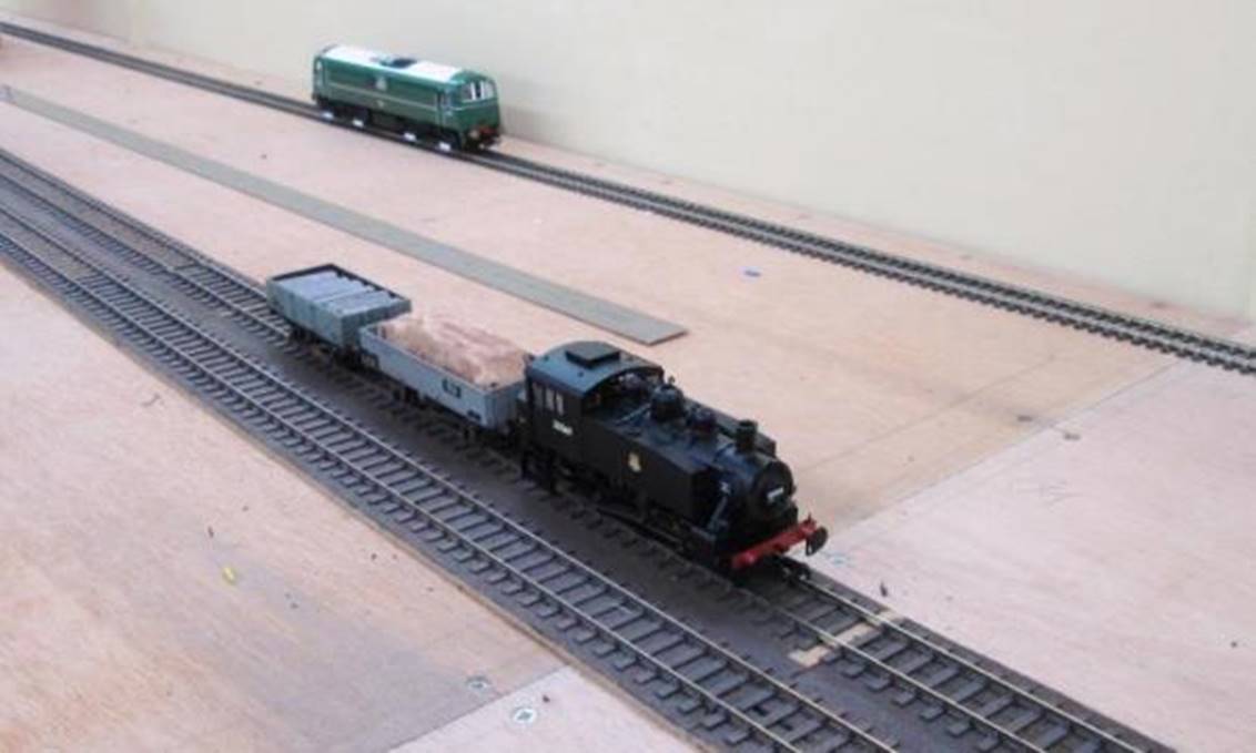
|
33 119 propels the Southern Region’s
Inspection Saloon TDB 975025 (converted from 6B buffet car 60755 from unit
no.1031 and released into use 1st November 1969). |
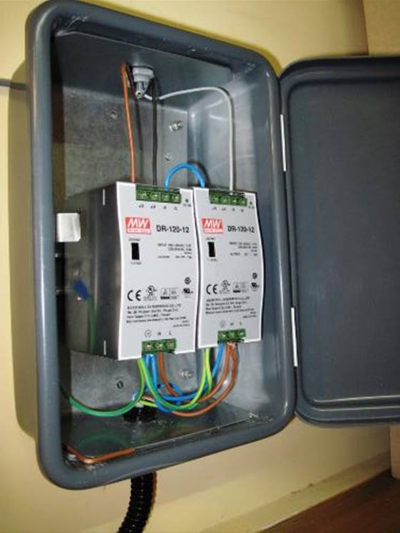
|
A thirties cross-country train formed of
signalman Arnold’s T9 no.312 hauling ex.LSWR
4 LAV set no.134. These coaches really are superb, arguably being one of the
most exciting releases in recent years. |

|
Locomotive 45 040 The King's Shropshire Light
Infantry takes a turn on a six-car train of mixed BR(S) Green Maunsell and
Bulleid 3-sets. On the Down line Delafilla’s
three PRESFO wagons and its COVHOP trundle by in a mixed freight train.
Originally ICI Salt Hoppers, these PRESFLO wagons carried slate dust from Delabole on the Southern’s North Cornwall line. |

|
Motorman Blakeman’s German Co-Co no.118
725. |
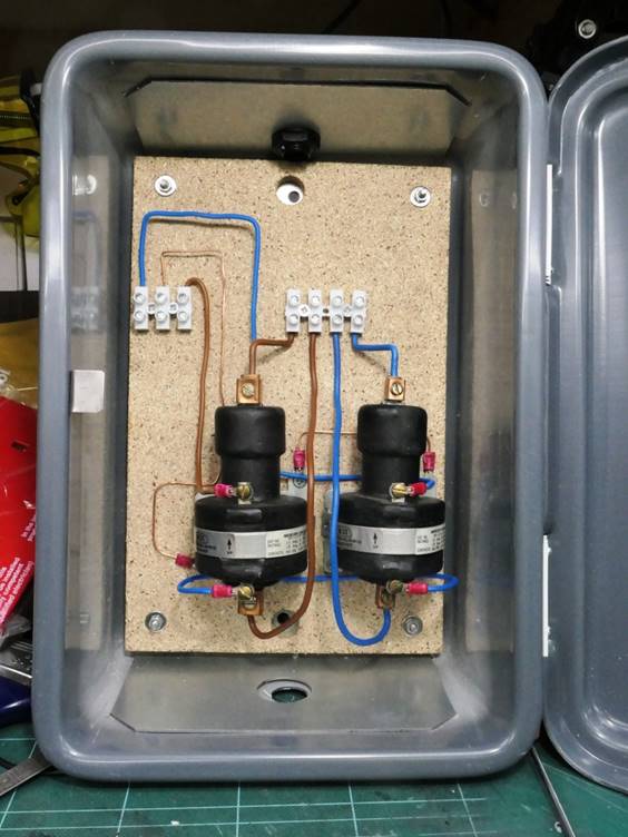
|
OO Works E4 class
no.32503 hauling |
|
WR Blue Pullman set came to stay for a few months. An absolute treat! |
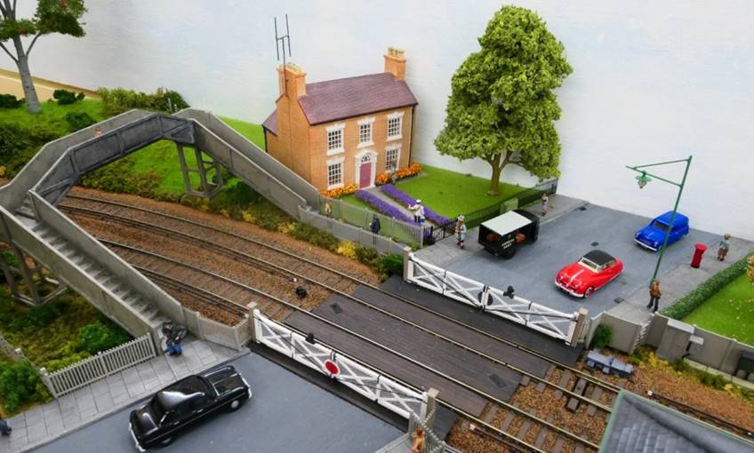
|
Roger Merry-Price’s B4, O2 and Beattie Well
Tank |

|
Merchant Navy number 35022 Holland America Line
hauls CLC-liveried Mk1 sets (with vans) on the Up Main as a van train speeds
past on the Down Main. Vans without Guard’s accommodation was always
positioned here as the Southern did not like swingers on the rear of its main
line trains. |

|
Personally, I find GWR outside framed locomotives
particularly elegant so Dukedog no.9003 was
welcomed as a visitor! |
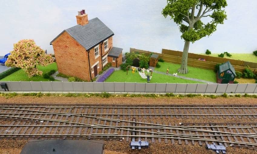
|
The Autumn evening sun makes the Crimson Lake
liveried pull-push set no.735 looks far more vivid that it really is. This
set worked in Surrey /Sussex (including the Horsham area) and here is being
hauled by a visiting H-tank. |
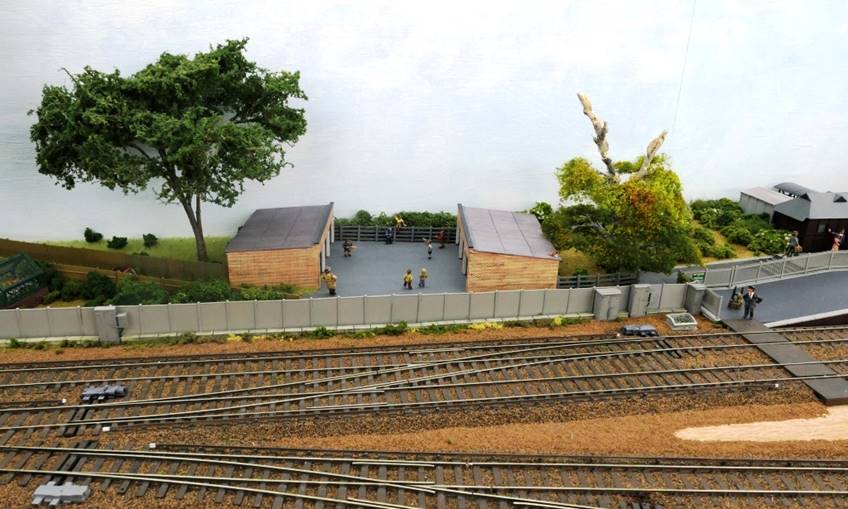
|
Originally the BRB would not permit Schools class
locomotives to receive passenger green livery as 4-4-0 locomotives were
considered as being obsolete. However, in July 1956 this decision was reversed
and in June 1959 number 30913 Christ’s Hospital was outshopped in lined
green livery. |
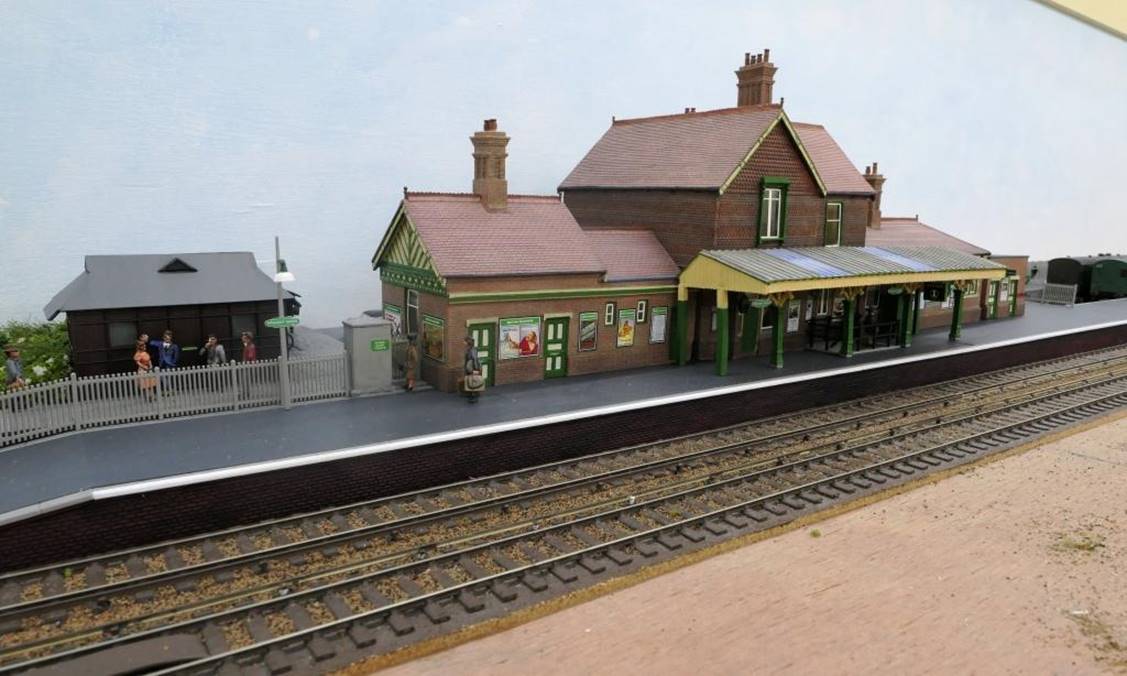
|
Visiting Warship D605 Cossack hauling an empty
petroleum /oil train on the Down Line. |
By March 2020 the pandemic had brought a halt to running sessions
and even with easing of social-distancing mid-2021 it was decided to wait until
2022 before deciding to recommence sessions with more than one fully-vaccinated
visitor in attendance. This was decision was also in line with all ESF members
deciding not to venture to any of the few model railway exhibitions being held
in the latter-part of 2021.
|
|
|
Ewhurst Green |
|
|
Route map shewing the
railway from Dorking |
33. Description of Railway Route
For those diehards who are interested it is
possible (but by no means certain) that the railway through Ewhurst Green took
the following route from Dorking North to Havant as follows:
|
1. |
From Dorking North the line used the
existing route south through to Holmwood. |
|
2. |
From Trouts
Junction (just south of Holmwood station where the Horsham line diverged to
head south) the line crossed Broomhill Road travelling down to cross Forest
Green Road. |
|
3. |
Crossing Lake Road and Mole Street Forest Green station was reached at
Horsham Road (Forest Green to Mayes Green). |
|
4. |
Lowerhouse Lane was crossed before
the level-crossing on Horsham Lane (Ewhurst to Walliswood)
and Ewhurst Green station more or
less on the site of Somersbury Manor. |
|
5. |
Passing under Somersbury
Lane the main line ran in between Longhurst Hill and Baynard’s Park;
the branch to Cranleigh having turned north-west to pass north of Vachery Pond having crossed Horsham Road (Ellens Green to
Cranleigh). |
|
6. |
As the branch to Cranleigh curved
north-west a ground frame provided access to the short spur which curved
sharply down alongside Vachery Lane thence through Snoxhall Farm and Lion’s Lane to Fast Bridge to the
MoD sidings squirreled away on the south-east side of the airfield. |
|
7. |
After crossing the Guildford to
Horsham railway close to the location of Baynards Station, Knowle Lane and
Horsham Road the station at Loxwood
was reached on a falling grade. |
|
8. |
Having crossed Loxwood Road there
was Gennets lattice viaduct which took the railway
across the Wey & Arun Junction Canal thence over Plaistow Road and Foxbridge Road into Plaistow
station which was sited closer to the (now) hamlet of Ifold. |
|
9. |
Continuing across Rickman’s
Lane the railway continued to Kirdford station located north of the village off
Scratchings Lane at Staples Hill. |
|
10. |
After Pipers Lane, the (now) A283 at
Colhook Common, Hillgrove Lane and River Lane, Lodsworth Station was reached at
Halfway Bridge. |
|
11. |
Crossing the (now) A272 the railway
crossed the River Rother before curving round to a new Midhurst Station which had been relocated between Midhurst and
West Lavington. |
|
12. |
Having crossed the (now) A286 the
line travelled south through Cocking
station to Singleton station and a
junction west of East Dean (where the line to Chichester turned left to turn
south). |
|
13. |
At East Dean the railway tunnelled
through Heathbarn Down, crossed the B2141 on Kingley Vale viaduct into another tunnel under Stoughton
Down to Stoughton & Walderton station (sited midway between the two
villages). |
|
14. |
After crossing the (now) B2147 and
crossing /re-crossing Aldsworth Common Road Westbourne station (off Monk’s
Hill) is reached. |
|
15. |
Long Copse
Lane, Southleigh Road and Horndean
Road are crossed before Denville Junction with the Chichester to Havant
railway is reached. |
This may be viewed as excessive detail. However, it
demonstrates such a railway route was feasible and in technical terms, could
have been built; therefore, supporting the credibility of the model. It was
also quite fun to research. Notwithstanding this, despite extensive searches
the remains of this route cannot be located!
However, by far the best fun came from playing hunt
the cat-biscuits with Moser.......
(A game derived from Moser hiding
Terry’s tea and biscuits)
|
In memory of Moser |
I hope this will have been of ongoing interest!
This webpage is kindly
provided by www.BloodandCustard.net
ALL TEXT
AND PHOTOGRAPHS ARE COPYRIGHT